Asus TUF B350M-PLUS GAMING User Guide - Page 14
PCI Express 2.0 x1 slot, Digital audio connector 4-1 pin SPDIF_OUT, M.2 socket 3, VGA configuration - cpu support
 |
View all Asus TUF B350M-PLUS GAMING manuals
Add to My Manuals
Save this manual to your list of manuals |
Page 14 highlights
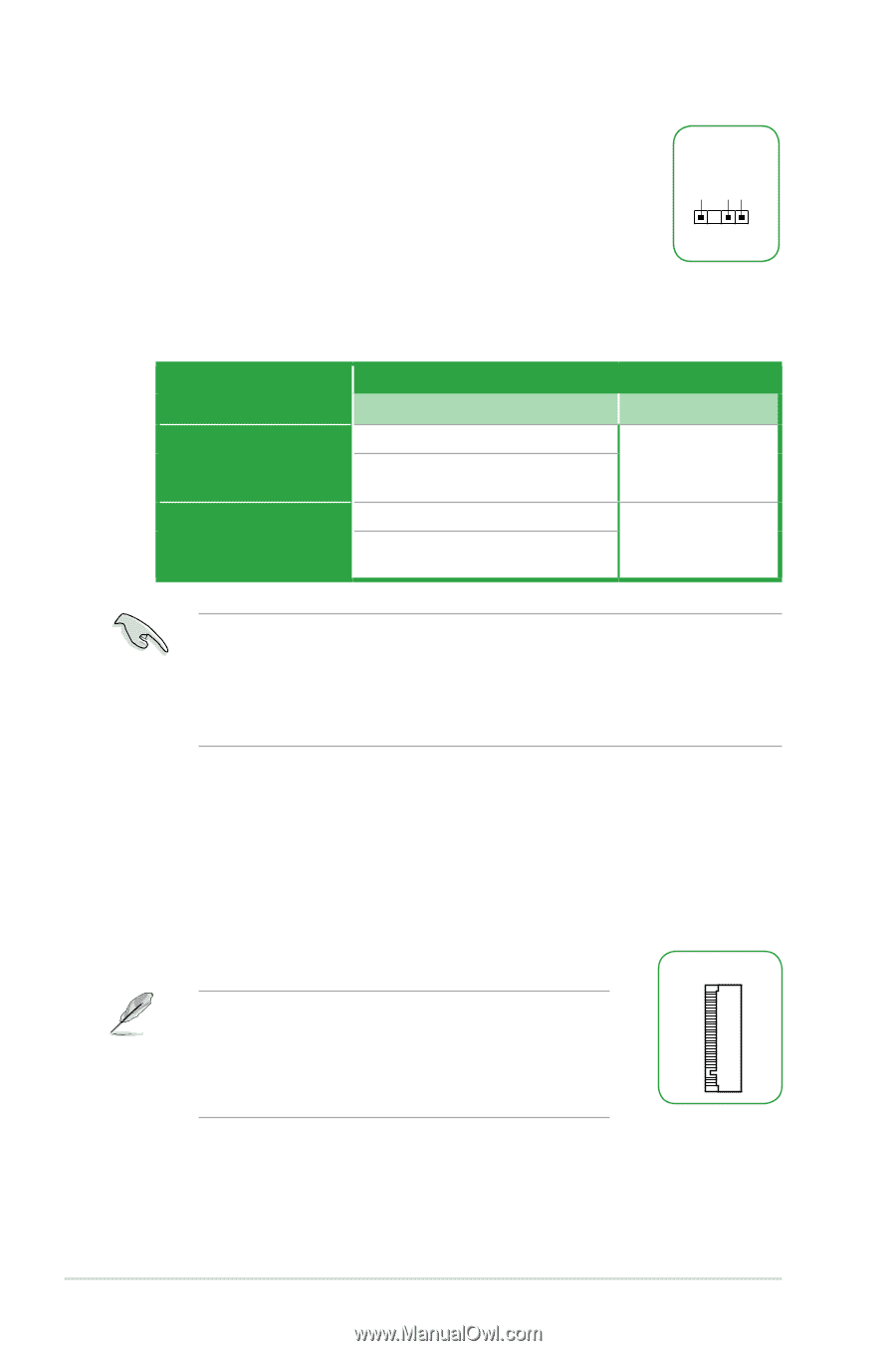
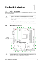
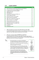
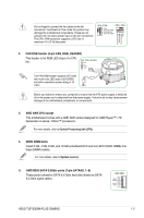
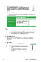
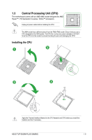
14. Digital audio connector (4-1 pin SPDIF_OUT) This connector is for an additional Sony/Philips Digital Interface (S/ PDIF) port. Connect the S/PDIF Out module cable to this connector, then install the module to a slot opening at the back of the system chassis. +5V SPDIFOUT GND SPDIF_OUT 15. PCI Express x16 slots This motherboard supports two PCI Express x16 graphic cards that comply with the PCI Express specifications. VGA configuration Single VGA/PCIe card Dual VGA/PCIe cards PCI Express operating mode PCIe 3.0/ 2.0 x16_1 (gray) x16 (on AMD Ryzen™ processors) x8 (on AMD 7th Generation A-series / Athlon™ processors) x16 (on AMD Ryzen™ processors) x8 (on AMD 7th Generation A-series / Athlon™ processors) PCIe 2.0 x16_2 N/A x4 • In single VGA card mode, use the PCIe 3.0/2.0 x16_1 slot (gray) for a PCI Express x16 graphics card to get better performance. • We recommend that you provide sufficient power when running CrossFireX™ mode. • Connect a chassis fan to the motherboard connector labeled CHA_FAN1/2 when using multiple graphics cards for better thermal environment. 16. PCI Express 2.0 x1 slot This motherboard has one PCI Express 2.0 x1 slot that supports PCI Express x1 network card, SCSI card, and other card that complies with the PCI Express specifications. 17. M.2 socket 3 These sockets allow you to install M.2 (NGFF) SSD modules. • This socket supports M Key and 2242/2260/2280 storage devices. • Due to CPU limitation, M.2 socket supported varies by processor. Refer to the specifications summary table for more details. M.2(SOCKET3) 1-6 Chapter 1: Product introduction
-
 1
1 -
2
-
3
-
4
-
5
-
6
-
7
-
8
-
 9
9 -
 10
10 -
 11
11 -
 12
12 -
 13
13 -
 14
14 -
 15
15 -
 16
16 -
 17
17 -
 18
18 -
 19
19 -
20
-
21
-
22
-
23
-
24
-
25
-
26
-
27
-
28
-
29
-
30
-
31
-
32
-
33
-
34
-
35
 |
 |