Asus TUF X299 MARK 1 TUF X299 MARK 1 Users ManualEnglish - Page 37
Thunderbolt header 5-pin TB_HEADER, VROC_HW_KEY connector 4-pin VROC_KEY
 |
View all Asus TUF X299 MARK 1 manuals
Add to My Manuals
Save this manual to your list of manuals |
Page 37 highlights
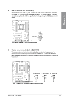
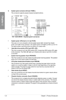
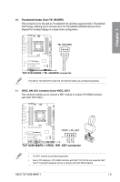
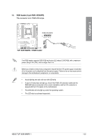
Chapter 1 10. Thunderbolt header (5-pin TB_HEADER) This connector is for the add-on Thunderbolt I/O card that supports Intel's Thunderbolt Technology, allowing you to connect up to six Thunderbolt-enabled devices and a DisplayPort-enabled display in a daisy-chain configuration. The add-on Thunderbolt I/O card and Thunderbolt cables are purchased separately. 11. VROC_HW_KEY connector (4-pin VROC_KEY) This connector allows you to connect a KEY module to enable CPU RAID functions with Intel® CPU RSTe. • The KEY module is purchased separately. • Due to CPU behavior, CPU RAID functions with Intel® CPU RSTe only supports Intel® Core™ X-series Processors (6-core or above) and Intel® SSD modules. ASUS TUF X299 MARK 1 1-21
-
 1
1 -
2
-
3
-
4
-
5
-
6
-
7
-
8
-
9
-
10
-
11
-
12
-
13
-
14
-
15
-
16
-
17
-
18
-
19
-
20
-
21
-
22
-
23
-
24
-
25
-
26
-
27
-
28
-
29
-
30
-
31
-
 32
32 -
 33
33 -
 34
34 -
 35
35 -
 36
36 -
 37
37 -
 38
38 -
 39
39 -
 40
40 -
 41
41 -
 42
42 -
43
-
44
-
45
-
46
-
47
-
48
-
49
-
50
-
51
-
52
-
53
-
54
-
55
-
56
-
57
-
58
-
59
-
60
-
61
-
62
-
63
-
64
-
65
-
66
-
67
-
68
-
69
-
70
-
71
-
72
-
73
-
74
-
75
-
76
-
77
-
78
-
79
-
80
-
81
-
82
-
83
-
84
-
85
-
86
-
87
-
88
-
89
-
90
-
91
-
92
-
93
-
94
-
95
-
96
-
97
-
98
-
99
-
100
-
101
-
102
-
103
-
104
-
105
-
106
-
107
-
108
-
109
-
110
-
111
-
112
 |
 |

ASUS TUF X299 MARK 1
1-21
Chapter 1
10.
Thunderbolt header (5-pin TB_HEADER)
This connector is for the add-on Thunderbolt I/O card that supports Intel’s Thunderbolt
Technology, allowing you to connect up to six Thunderbolt-enabled devices and a
DisplayPort-enabled display in a daisy-chain configuration.
The add-on Thunderbolt I/O card and Thunderbolt cables are purchased separately.
11.
VROC_HW_KEY connector (4-pin VROC_KEY)
This connector allows you to connect a KEY module to enable CPU RAID functions
with Intel
®
CPU RSTe.
•
The KEY module is purchased separately.
•
Due to CPU behavior, CPU RAID functions with Intel
®
CPU RSTe only supports Intel
®
Core™ X-series Processors (6-core or above) and Intel
®
SSD modules.