Asus V2-P5G33 User Manual - Page 41
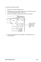
Re-connecting cables
 |
UPC - 610839743810
View all Asus V2-P5G33 manuals
Add to My Manuals
Save this manual to your list of manuals |
Page 41 highlights
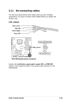
2.11 Re-connecting cables You may have disconnected some cables when you were installing components. You must re-connect these cables before you replace the chassis cover. LED cables Reset button HDD LED Power Switch Power LED PLED+ PLED+ PPPLWLERED-DGND +5V Ground Ground Speaker P5K-VM PWR PLELDEDPWRSPBETNAKER ® M2N-NM FF__PPAANNEELL R IDE_LED+ IDIIEDD_EELLLEEEDDD--+ Ground Reset PWR Ground Reset Ground System Panel Connector P5K-VM System panel connector HD ILDEED_LREEDSET RESET PWRSW * Requires an ATX power supply. Connect the reset button, power switch, power LED, and HDD LED cables to their respective leads in the system panel connector on the motherboard. ASUS V-Series P5G33 2-23
-
 1
1 -
2
-
3
-
4
-
5
-
6
-
7
-
8
-
9
-
10
-
11
-
12
-
13
-
14
-
15
-
16
-
17
-
18
-
19
-
20
-
21
-
22
-
23
-
24
-
25
-
26
-
27
-
28
-
29
-
30
-
31
-
32
-
33
-
34
-
35
-
 36
36 -
 37
37 -
 38
38 -
 39
39 -
 40
40 -
 41
41 -
 42
42 -
 43
43 -
 44
44 -
 45
45 -
 46
46 -
47
-
48
-
49
-
50
-
51
-
52
-
53
-
54
-
55
-
56
-
57
-
58
-
59
-
60
-
61
-
62
-
63
-
64
-
65
-
66
-
67
-
68
-
69
-
70
-
71
-
72
-
73
-
74
-
75
-
76
-
77
-
78
-
79
-
80
-
81
-
82
-
83
-
84
-
85
-
86
-
87
-
88
-
89
-
90
-
91
-
92
-
93
-
94
-
95
-
96
-
97
-
98
-
99
-
100
-
101
-
102
-
103
-
104
-
105
-
106
 |
 |

2-23
ASUS V-Series P5G33
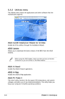
2.11 Re-connecting cables
You may have disconnected some cables when you were installing
components. You must re-connect these cables before you replace the
chassis cover.
LED cables
Connect the
reset button,
power switch,
power LED, and
HDD LED
cables to their respective leads in the system panel connector on the
motherboard.
HDD LED
Power LED
Power Switch
Reset button
I
P5K-VM
P5K-VM System panel connector
F_P
PANEL
PLED-
PWR
PLED+
Ground
GND
Reset
IDELED+
IDELED-
HD
LED
RESET
PWR LED
PWR BTN