Asus V2-P5G33 User Manual - Page 69
System power LED 2-pin PLED
 |
UPC - 610839743810
View all Asus V2-P5G33 manuals
Add to My Manuals
Save this manual to your list of manuals |
Page 69 highlights
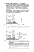
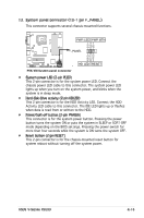
13. System panel connector (10-1 pin F_PANEL) This connector supports several chassis-mounted functions. PLED+ PLPLEEDD+PLEDPWR GND +5V Ground Ground Speaker P5K-VM PWRPLLEEDD PSWPERABKTENR ® M2N-NM R FF__PPAANNEELL IDE_LED+ IDE_LEDIDELED+ IDELEDGround ResPetWR Ground Reset Ground SyPs5tKem-VMPaSnyeslteCmopnanneecltcoornnector HDIDELE_LDEDRESREETSET PWRSW * Requires an ATX power supply. • System power LED (2-pin PLED) This 2-pin connector is for the system power LED. Connect the chassis power LED cable to this connector. The system power LED lights up when you turn on the system power, and blinks when the system is in sleep mode. • Hard disk drive activity (2-pin HDLED) This 2-pin connector is for the HDD Activity LED. Connect the HDD Activity LED cable to this connector. The IDE LED lights up or flashes when data is read from or written to the HDD. • Power/Soft-off button (2-pin PWRSW) This connector is for the system power button. Pressing the power button turns the system ON or puts the system in SLEEP or SOFT-OFF mode depending on the BIOS settings. Pressing the power switch for more than four seconds while the system is ON turns the system OFF. • Reset button (2-pin RESET) This 2-pin connector is for the chassis-mounted reset button for system reboot without turning off the system power. ASUS V-Series P5G33 4-13
-
 1
1 -
2
-
3
-
4
-
5
-
6
-
7
-
8
-
9
-
10
-
11
-
12
-
13
-
14
-
15
-
16
-
17
-
18
-
19
-
20
-
21
-
22
-
23
-
24
-
25
-
26
-
27
-
28
-
29
-
30
-
31
-
32
-
33
-
34
-
35
-
36
-
37
-
38
-
39
-
40
-
41
-
42
-
43
-
44
-
45
-
46
-
47
-
48
-
49
-
50
-
51
-
52
-
53
-
54
-
55
-
56
-
57
-
58
-
59
-
60
-
61
-
62
-
63
-
 64
64 -
 65
65 -
 66
66 -
 67
67 -
 68
68 -
 69
69 -
 70
70 -
 71
71 -
 72
72 -
 73
73 -
 74
74 -
75
-
76
-
77
-
78
-
79
-
80
-
81
-
82
-
83
-
84
-
85
-
86
-
87
-
88
-
89
-
90
-
91
-
92
-
93
-
94
-
95
-
96
-
97
-
98
-
99
-
100
-
101
-
102
-
103
-
104
-
105
-
106
 |
 |
