Asus WS C246M PRO User Manual - Page 15
Layout contents, Connectors/Jumpers/Buttons and switches/Slots
 |
View all Asus WS C246M PRO manuals
Add to My Manuals
Save this manual to your list of manuals |
Page 15 highlights
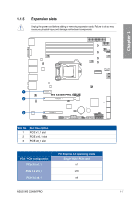
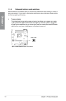
Chapter 1 Layout contents Connectors/Jumpers/Buttons and switches/Slots 1. DDR4 DIMM slots 2. ATX power connectors (24-pin EATXPWR1; 8-pin EATX12V1) 3. Smart Ride Through (SmaRT) setting (3-pin SMART_PSU1) 4. Power Supply SMBus connector (5-pin PSUSMB1) 5. System Management Bus (SMBUS) connector (5-1 pin SMBUS1) 6. Fan connectors (4-pin CPU_FAN1; 4-pin FRNT_FAN1-3; 4-pin REAR_FAN1) 7. M.2 (NGFF) connector (NGFF1) 8. USB 2.0 connectors (10-1 pin USB34, USB78) 9. BIOS Flashback button 10. ME firmware force recovery setting (3-pin ME_RCVR1) 11. Intel® Serial ATA 6 Gb/s connectors (7-pin SATA6G_1-8) 12. Serial General Purpose Input/Output connector (6-1 pin SGPIO1) 13. Auxiliary panel connector (20-2 pin AUX_PANEL1) 14. System panel connector (20-1 pin PANEL1) 15. PCH_MFG1 setting (3-pin PCH_MFG1) 16. USB 3.1 Gen 1 connector (20-1 pin USB3_12) 17. Storage device activity LED connector (4-pin HDLED1) 18. Chassis Intrusion (2-pin INTRUSION1) 19. Q-Code LED 20. Serial port connector (10-1 pin COM1) 21. TPM connector (14-1 pin TPM1) 22. Digital audio connector (4-1 pin SPDIF_OUT1) 23. Front panel audio connector (10-1 pin AAFP) 24. Clear RTC RAM (3-pin CLRTC1) 25. Thermal sensor cable connector (3-pin TR1) 26. Power-on button 27. LGA1151 CPU socket 28. LAN controller setting (3-pin LAN_SW2) Page 1-5 1-23 1-11 1-24 1-25 1-20 1-26 1-19 2-11 1-10 1-16 1-24 1-22 1-21 1-11 1-18 1-19 1-25 1-15 1-18 1-17 1-20 1-17 1-9 1-22 1-8 1-4 1-10 ASUS WS C246M PRO 1-3
-
 1
1 -
2
-
3
-
4
-
5
-
6
-
7
-
8
-
9
-
 10
10 -
 11
11 -
 12
12 -
 13
13 -
 14
14 -
 15
15 -
 16
16 -
 17
17 -
 18
18 -
 19
19 -
 20
20 -
21
-
22
-
23
-
24
-
25
-
26
-
27
-
28
-
29
-
30
-
31
-
32
-
33
-
34
-
35
-
36
-
37
-
38
-
39
-
40
-
41
-
42
-
43
-
44
-
45
-
46
-
47
-
48
-
49
-
50
-
51
-
52
-
53
-
54
-
55
-
56
-
57
-
58
-
59
-
60
-
61
-
62
-
63
-
64
-
65
-
66
-
67
-
68
-
69
-
70
-
71
-
72
-
73
-
74
-
75
-
76
-
77
-
78
-
79
-
80
-
81
-
82
-
83
-
84
-
85
-
86
-
87
-
88
-
89
-
90
-
91
-
92
-
93
-
94
-
95
-
96
-
97
-
98
-
99
-
100
-
101
-
102
-
103
-
104
-
105
-
106
-
107
-
108
-
109
-
110
-
111
-
112
-
113
-
114
-
115
-
116
-
117
-
118
-
119
-
120
-
121
-
122
-
123
-
124
 |
 |
