Asus XG-DLS User Manual - Page 12
Iii. Installation
 |
View all Asus XG-DLS manuals
Add to My Manuals
Save this manual to your list of manuals |
Page 12 highlights
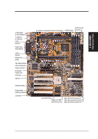
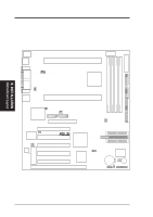
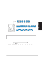
PARALLEL PORT BF0 BF1 BF2 BF3 III. INST ALLATION Motherboard Layout III. INSTALLATION ASUS XG-DLS Motherboard Layout ATXPWR SECONDARY IDE DIMM Socket 4 (64/72 bit, 168 pin module) DIMM Socket 3 (64/72 bit, 168 pin module) DIMM Socket 2 (64/72 bit, 168 pin module) DIMM Socket 1 (64/72 bit, 168 pin module) PS/2 TOP: Mouse BOTTOM: Keyboard USB TOP: USB 1 BOTTOM: USB 2 COM1 PWR_FAN Slot 2 Connector (for Intel® Xeon™ Processor) CPU1TEMP Intel® 440GX AGPset COM2 RJ-45 CHA_FAN Slot 2 Connector (for Intel® Xeon™ Processor) PWR3V PRIMARY IDE Intel® FastEthernet Chipset CPU0TEMP FLOPPY CPU_FAN XG-DLS AGP (Accelerated Graphics Port) ROW 0 1 2 3 4 5 6 7 FS0 FS1 FS2 BUS FREQ Multi-I/O, Keyboard Controller SB-LINK Hardware Monitor Motherboard Thermal Sensor PCI1 (PCI Slot 1) WOL_CON PCI2 (PCI Slot 2) PCI3 (PCI Slot 3) PCI4 (PCI Slot 4) Flash EEPROM (Programable BIOS) PCI5 (PCI Slot 5) ISA Slot 1 (ISA1) R Adaptec® Ultra-Fast (50-Pin) SCSI Connector AIC-7896 (Channel B) 1 Dual Chan. Chipset Ultra2 (68-Pin)SCSI Connector (Channel A) 35 68 1 34 35 68 1 34 Ultra2 (68-Pin)SCSI Connector (Channel B) Intel® PIIX4E PCIset CHASSIS (Intrusion) ASUS ASIC CR2032 3V Lithium Cell (BIOSPower) Freq Mult Buzzer CLRTC IR HDLED PANEL Connectors 12 ASUS XG-DLS User's Manual
-
 1
1 -
2
-
3
-
4
-
5
-
6
-
 7
7 -
 8
8 -
 9
9 -
 10
10 -
 11
11 -
 12
12 -
 13
13 -
 14
14 -
 15
15 -
 16
16 -
 17
17 -
18
-
19
-
20
-
21
-
22
-
23
-
24
-
25
-
26
-
27
-
28
-
29
-
30
-
31
-
32
-
33
-
34
-
35
-
36
-
37
-
38
-
39
-
40
 |
 |
