Asus Z9PE-D8 WS User Guide - Page 28
Layout contents, Rear panel connectors, Jumpers, Slots/Socket, Onboard Switches, Onboard LEDs - ram
 |
View all Asus Z9PE-D8 WS manuals
Add to My Manuals
Save this manual to your list of manuals |
Page 28 highlights
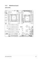
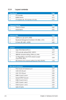
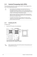
2.2.4 Layout contents Slots/Socket 1. CPU sockets 2. DDR3 sockets 3. PCI Express x8 / PCI Express x16 slots Onboard Switches 1. Power-on Switch 2. Reset Switch Onboard LEDs 1. DIMM Error LED (ERR_DIMM) 2. Baseboard Management Controller LED (BMC_LED1) 3. Q-Code LED (LED1_LED2) Jumpers 1. Clear RTC RAM (CLRTC1) 2. VGA controller setting (DIAG_VIEW1) 3. SMBUS connection setting (TESLA_M_SW) 4. LSI MegaRAID or Intel RSTe selection jumper (3-pin RAID_SEL1) 5. ME firmware force recovery setting (3-pin ME_RCVR1) Rear panel connectors 1. PS/2 mouse and keyboard port 2. LAN 2 (RJ-45) port 3. LAN 1 (RJ-45) port 4. USB 2.0 ports 5 and 6 5. Optical S/PDIF Out port 6. USB 2.0 ports 3 and 4 7. USB 2.0 ports 1 and 2 8. USB 3.0 ports 1 and 2 9. Audio I/O ports Page 2-8 2-13 2-16 Page 2-20 2-20 Page 2-21 2-21 2-22 Page 2-26 2-27 2-27 2-28 2-28 Page 2-29 2-29 2-29 2-29 2-29 2-29 2-29 2-29 2-29 2-6 Chapter 2: Hardware information
-
 1
1 -
2
-
3
-
4
-
5
-
6
-
7
-
8
-
9
-
10
-
11
-
12
-
13
-
14
-
15
-
16
-
17
-
18
-
19
-
20
-
21
-
22
-
 23
23 -
 24
24 -
 25
25 -
 26
26 -
 27
27 -
 28
28 -
 29
29 -
 30
30 -
 31
31 -
 32
32 -
 33
33 -
34
-
35
-
36
-
37
-
38
-
39
-
40
-
41
-
42
-
43
-
44
-
45
-
46
-
47
-
48
-
49
-
50
-
51
-
52
-
53
-
54
-
55
-
56
-
57
-
58
-
59
-
60
-
61
-
62
-
63
-
64
-
65
-
66
-
67
-
68
-
69
-
70
-
71
-
72
-
73
-
74
-
75
-
76
-
77
-
78
-
79
-
80
-
81
-
82
-
83
-
84
-
85
-
86
-
87
-
88
-
89
-
90
-
91
-
92
-
93
-
94
-
95
-
96
-
97
-
98
-
99
-
100
-
101
-
102
-
103
-
104
-
105
-
106
-
107
-
108
-
109
-
110
-
111
-
112
-
113
-
114
-
115
-
116
-
117
-
118
-
119
-
120
-
121
-
122
-
123
-
124
-
125
-
126
-
127
-
128
-
129
-
130
-
131
-
132
-
133
-
134
-
135
-
136
-
137
-
138
-
139
-
140
-
141
-
142
-
143
-
144
-
145
-
146
-
147
-
148
-
149
-
150
-
151
-
152
-
153
-
154
-
155
-
156
-
157
-
158
-
159
-
160
-
161
-
162
-
163
-
164
-
165
-
166
-
167
-
168
-
169
-
170
-
171
-
172
-
173
-
174
-
175
-
176
-
177
-
178
-
179
-
180
-
181
-
182
-
183
-
184
-
185
-
186
-
187
-
188
-
189
-
190
-
191
-
192
-
193
-
194
-
195
-
196
-
197
-
198
-
199
-
200
-
201
-
202
-
203
-
204
-
205
-
206
-
207
-
208
-
209
-
210
-
211
-
212
-
213
-
214
-
215
-
216
-
217
-
218
-
219
-
220
-
221
-
222
-
223
-
224
-
225
-
226
 |
 |