Asus a7n8xx Motherboard DIY Troubleshooting Guide - Page 14
Super I/O chipset. - bios
 |
View all Asus a7n8xx manuals
Add to My Manuals
Save this manual to your list of manuals |
Page 14 highlights
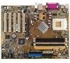
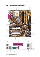
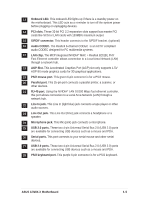
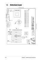
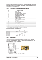
1 CPU Sockets. Socket 462 (Socket A) Zero Insertion Force (ZIF) socket for the AMD Duron™/Athlon™/Athlon XP™ 3000+ processors. 2 NorthBridge Controller. The NVIDIA® nForce2™ 400 North Bridge controller chipset. The controller supports a 64-bit DDR memory controller and up to 3 GB of 400/333/266/200MHz DDR memory. 3 DDR DIMM Sockets. Equipped with three Double Data Rate Dual Inline Memory Module (DDR DIMM) sockets to support up to 3GB of DDR DRAM, the newest memory standard with the highest bandwidth and lowest latency currently available. This memory technology supplies data transfer rates up to 3.2 GB/s for 400MHz DDR SDRAM and 2.7GB/s for 333MHz DDR SDRAM. 4 ATX power connector. This standard 20-pin connector connects to an ATX 12V power supply. The power supply must have at least 1A on the +5V standby lead (+5VSB). 5 Floppy Disk connector. This connector connects the provided ribbon cable for the floppy disk drive. One side of the connector is slotted to prevent incorrect insertion of the floppy disk cable. 6 IDE Connectors. These dual-channel bus master IDE connectors support up to four Ultra DMA133/100/66, PIO Modes 3 & 4 IDE devices. Both the primary(blue) and secondary(black) connectors are slotted to prevent incorrect insertion of the IDE ribbon cable. 7 Flash ROM. This 2Mb firmware contains the programmable BIOS program. (Refer to section "2.1 Managing and updating your BIOS" on page 2-2 for more information) 8 South bridge controller. Features the brand new nVidia® nForce2™ MCP integrated peripheral South Bridge controller operates at 800MB/sec to communicate with the North Bridge for maximum bandwith required for PCI, USB and support for Fast Ethernet devices. The controller supports standard UltraDMA133/100/66/33 and separate data paths for each IDE channel are built-in for up to two IDE devices. The controller supports six USB ports, one LAN port and is PCI rev2.2 compliant. 9 Super I/O chipset. ITE IT8708 offers support for a variety of I/O functions. Provides two high-speed UART compatible serial ports and one parallel port with EPP and ECP capabilities. UART2 can also be directed from COM2 to the Infrared Module for wireless connections. The Super I/O controller supports a floppy disk drive, PS/2 keyboard, and PS/2 mouse. 10 COM2 Header. This 9-pin connects to a COM2 port. 11 GAME port header. This header connects to a GAME port module. 12 ASUS ASIC. This chip performs multiple system functions that include hardware and system voltage monitoring among others. 1-4 Chapter 1: Motherboard Information
-
 1
1 -
2
-
3
-
4
-
5
-
6
-
7
-
8
-
 9
9 -
 10
10 -
 11
11 -
 12
12 -
 13
13 -
 14
14 -
 15
15 -
 16
16 -
 17
17 -
 18
18 -
 19
19 -
20
-
21
-
22
-
23
-
24
-
25
-
26
-
27
-
28
-
29
-
30
-
31
-
32
-
33
-
34
-
35
-
36
-
37
-
38
-
39
-
40
-
41
-
42
-
43
-
44
-
45
-
46
-
47
-
48
-
49
-
50
-
51
-
52
-
53
-
54
-
55
-
56
-
57
-
58
-
59
-
60
 |
 |