Audiovox AW871 Operation Manual - Page 3
I. Location of Functions - speakers
 |
UPC - 044102150874
View all Audiovox AW871 manuals
Add to My Manuals
Save this manual to your list of manuals |
Page 3 highlights
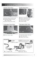
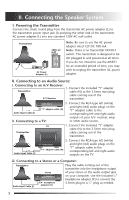
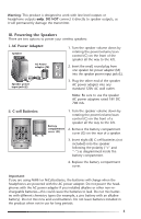
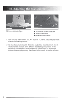
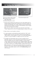
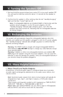
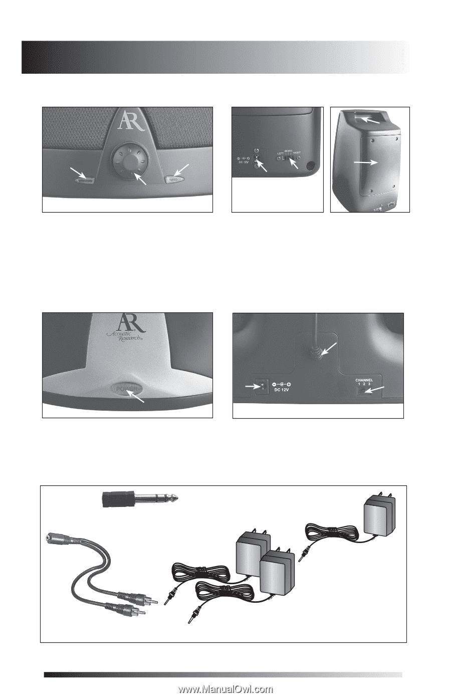
I. Location of Functions Speaker Front View: Speaker Back View: G B A D EF C A. Tuning indicator light (tuned) B. Standby/Charging indicator light (stdby/chrg) C. Power/volume/scan control D. Battery compartment cover E. Speaker power input jack F. Left/mono/right switch G. Carrying handle Transmitter Front View: Transmitter Back View: J H H. Power indicator light I K I. Transmitter power input jack J. Audio input cable K. Channel select switch Accessories: IMPORTANT: These power units are intended to be correctly inserted in a O. 1/4" headphone adapter vertical or floor mount position. dio Output L. Transmitter AC power adapter - 12V DC N. "Y" adapter cable M. Speaker AC power adapter (x2) - 18V DC 2
-
 1
1 -
 2
2 -
 3
3 -
 4
4 -
 5
5 -
 6
6 -
 7
7 -
 8
8 -
 9
9 -
10
-
11
-
12
 |
 |
2
I. Location of Functions
Speaker Front View:
A.
Tuning indicator light (tuned)
B.
Standby/Charging indicator
light (stdby/chrg)
C.
Power/volume/scan control
Transmitter Front View:
H.
Power indicator light
Accessories:
Speaker Back View:
D.
Battery compartment cover
E.
Speaker power input jack
F.
Left/mono/right switch
G.
Carrying handle
Transmitter Back View:
I.
Transmitter power input jack
J.
Audio input cable
K.
Channel select switch
L.
Transmitter AC
power adapter
- 12V DC
O.
1
/
4
” headphone adapter
N.
“Y” adapter cable
M.
Speaker AC power
adapter (x2) - 18V DC
A
B
C
H
I
K
J
E
F
D
G
IMPORTANT:
These power units are
intended to be correctly inserted in a
vertical or floor mount position.