Audiovox D1805 User Manual - Page 5
E. Controls, Indicators, and Connectors, - battery
 |
View all Audiovox D1805 manuals
Add to My Manuals
Save this manual to your list of manuals |
Page 5 highlights
E. Controls, Indicators, and Connectors 1. Unit View (Refer to Figure 2) 1) DC 9V Input Jack 2) Audio Jack (L+R) 3) Video Jack 4) AV Input /Output Switch 5) Brightness Control 6) MENU 7) Up button 8) Left Button 9) OK Button 10) Down Button 11) Right Button 12) Close disc cover point 13) Open Button 14) Previous Button 15) Stop Button 16) Next Button 17) Play Button 18) Pause Button 19) Screen Mode ( wide) Button 20) Power Saving Mode Switch Figure 2 21) NTSC/PAL Switch 22) Coaxial Jack 23) Hi-Fi Headphone Jack 24) Volume Control 25) Power On/ Off Switch 26) Remote Control Sensor 27) Power LED 28) Battery Clips 29) Battery Connector 5
-
 1
1 -
 2
2 -
 3
3 -
 4
4 -
 5
5 -
 6
6 -
 7
7 -
 8
8 -
 9
9 -
 10
10 -
 11
11 -
12
-
13
-
14
-
15
-
16
-
17
-
18
-
19
-
20
-
21
-
22
-
23
-
24
-
25
-
26
-
27
-
28
-
29
-
30
-
31
-
32
-
33
 |
 |

5
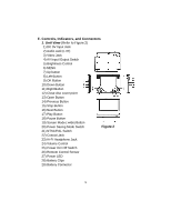
E. Controls, Indicators, and Connectors
1. Unit View
(Refer to Figure 2)
1) DC 9V Input Jack
2) Audio Jack (L+R)
3) Video Jack
4) AV Input /Output Switch
5) Brightness Control
6) MENU
7) Up button
8) Left Button
9) OK Button
10) Down Button
11) Right Button
12) Close disc cover point
13) Open Button
14) Previous Button
15) Stop Button
16) Next Button
17) Play Button
18) Pause Button
19) Screen Mode ( wide) Button
20) Power Saving Mode Switch
21) NTSC/PAL Switch
22) Coaxial Jack
23) Hi-Fi Headphone Jack
24) Volume Control
25) Power On/ Off Switch
26) Remote Control Sensor
27) Power LED
28) Battery Clips
29) Battery Connector
Figure 2