Audiovox D1817 Owners Manual - Page 8
F. Controls, Indicators, and Connectors,
 |
UPC - 044476039911
View all Audiovox D1817 manuals
Add to My Manuals
Save this manual to your list of manuals |
Page 8 highlights
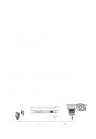
F. Controls, Indicators, and Connectors 1. Unit View (Refer to Figure 3) Figure 3 1) LCD Panel Shut Off Switch 2) Wide Button 3) Stop Button 4) Previous Button 5) Next Button 6) Play Button 7) Menu Button 8) Up Button 9) Right Button 10) OK Button 11) Down Button 12) Left Button 13) Open Door Switch 14) IR Sensor 15) Power LED 16) Power on/off Switch 17) Brightness Up/Down Control 18) Volume Up/Down Control 19) Headphone 1* 20) Headphone 2 21) E-Port 22) AV IN/OUT Switch 23) AV Jack 24) DC 9-12V Input Jack *Using headphone jack 1 will disable the internal speakers 8
-
 1
1 -
2
-
 3
3 -
 4
4 -
 5
5 -
 6
6 -
 7
7 -
 8
8 -
 9
9 -
 10
10 -
 11
11 -
 12
12 -
 13
13 -
14
-
15
-
16
-
17
-
18
-
19
-
20
-
21
-
22
-
23
-
24
-
25
-
26
-
27
-
28
-
29
-
30
-
31
-
32
-
33
-
34
-
35
-
36
-
37
-
38
-
39
 |
 |

8
F. Controls, Indicators, and Connectors
1. Unit View
(Refer to Figure 3)
Figure 3
*Using headphone jack 1 will disable the internal speakers
1) LCD Panel Shut Off Switch
2) Wide Button
3) Stop Button
4) Previous Button
5) Next Button
6) Play Button
7) Menu Button
8) Up Button
9) Right Button
10) OK Button
11) Down Button
12) Left Button
13) Open Door Switch
14) IR Sensor
15) Power LED
16) Power on/off Switch
17) Brightness Up/Down Control
18) Volume Up/Down Control
19) Headphone 1*
20) Headphone 2
21) E-Port
22) AV IN/OUT Switch
23) AV Jack
24) DC 9-12V Input Jack