Behringer COMPOSER PRO-XL MDX2600 Manual - Page 11
Installation - how to use
 |
View all Behringer COMPOSER PRO-XL MDX2600 manuals
Add to My Manuals
Save this manual to your list of manuals |
Page 11 highlights
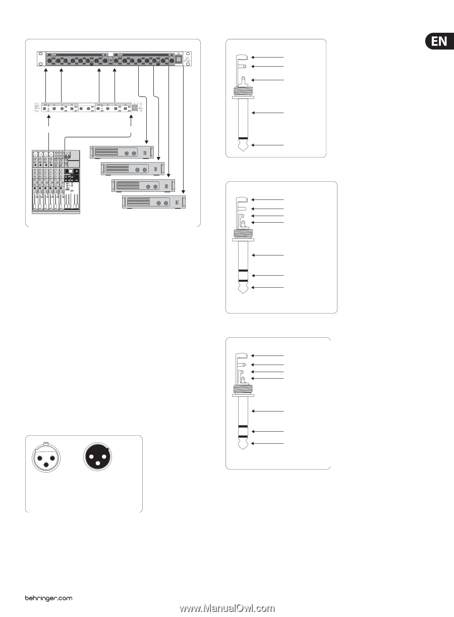
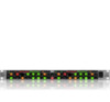
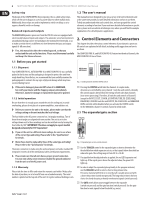
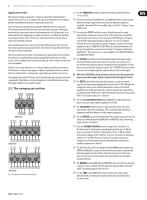
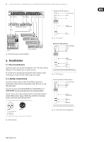
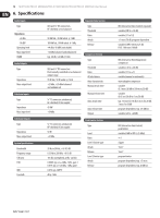
11 MULTICOM PRO-XL MDX4600/PRO-XL MDX2600/AUTOCOM PRO-XL MDX1600 User Manual MULTICOM PRO-XL MDX4600 Ch1 Ch2 Ch3 Ch4 Ch1 Ch2 Ch3 Ch4 Hi Low Hi Low Input SUPER-X PRO CX2310 Input L R Unbalanced ¼" TS connector strain relief clamp sleeve tip sleeve (ground/shield) tip (signal) Fig. 5.2: 1/4" TS connector Mixer Power ampli ers Fig. 4.3: Multi-band compression with the MDX4600 5. Installation 5.1 Rack installation Each device requires one rack unit for installation in a 19" rack. Please allow an additional 4" of rack depth for the rear panel connectors. Be sure that there is enough air space around the unit for cooling. To avoid overheating, do not place the unit on power amps, for example. 5.2 Audio connections You will need a large number of cables for the different applications. The illustrations below show the wiring of these cables. Be sure to use only high-grade cables. The audio connections of the MULTICOM PRO-XL, AUTOCOM PRO-XL and COMPOSER PRO-XL are electronically balanced to avoid hum problems. You can, of course, also connect unbalanced devices to the balanced inputs/ outputs. Either use mono plugs, or link the ring and shaft on stereo plugs (or pins 1 and 3 in the case of XLR connectors). 21 3 12 3 input output 1 = ground/shield 2 = hot (+ve) 3 = cold (-ve) For unbalanced use, pin 1 and pin 3 have to be bridged Fig. 5.1: XLR connections Balanced ¼" TRS connector strain relief clamp sleeve ring tip sleeve ground/shield ring cold (-ve) tip hot (+ve) For connection of balanced and unbalanced plugs, ring and sleeve have to be bridged at the stereo plug. Fig. 5.3: 1/4" TRS connector Insert send return ¼" TRS connector strain relief clamp sleeve ring tip sleeve ground/shield ring return (in) tip send (out) Connect the insert send with the input and the insert return with the output of the e ects device. Fig. 5.4: 1/4" TRS connector for insert applications
-
 1
1 -
2
-
3
-
4
-
5
-
 6
6 -
 7
7 -
 8
8 -
 9
9 -
 10
10 -
 11
11 -
 12
12 -
 13
13 -
 14
14 -
 15
15
 |
 |