Behringer COMPOSER PRO-XL MDX2600 Manual - Page 9
Examples of Sidechain, Applications - compressor limiter
 |
View all Behringer COMPOSER PRO-XL MDX2600 manuals
Add to My Manuals
Save this manual to your list of manuals |
Page 9 highlights
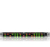
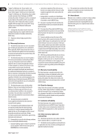
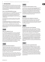
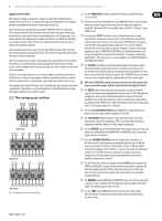
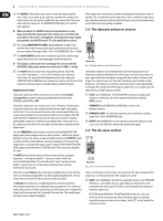
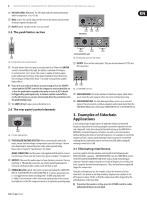
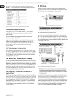
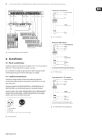
9 MULTICOM PRO-XL MDX4600/PRO-XL MDX2600/AUTOCOM PRO-XL MDX1600 User Manual (26) DE-ESSER LEVEL (MDX2600). The LED chain reads the current attenuation within a range from +3 to +12 dB. (27) MALE switch. This switch adapts the de-esser to the male (switch pressed) or female registers (not pressed). (28) IN/OUT switch. Switches the de-esser on and off. 2.5 The peak limiter section (30) (32) (33) (34) MDX4600 (32) (33) (34) MDX2600/MDX1600 (29) Fig. 2.8: Rear panel connectors and switches Fig. 2.6: Peak limiter section control elements (29) The peak limiter limits the signal to an adjustable level. When the LIMITER control is turned fully to the right, the limiter is switched off. Owing to its extremely fast "zero" attack, this circuit is capable of limiting signal peaks without any overshoot. If the signal is limited for more than 20 ms, the overall gain is reduced for about 1 s to avoid strong and thus audible limiter effects. ◊ If you wish to use the peak limiter as a protecting device, the LIMITER control and the OUTPUT control in the compressor section should be set so that the peak limiter responds only rarely or never at all. It should be triggered by peak signals only. To achieve creative sound effects, on the other hand, you can also intentionally drive the peak limiter into this peak limiting range. (30) The LIMIT LED lights up as soon as the limiter is on. 2.6 The rear panel control elements (34) INPUTS. These are the audio inputs. They are also on balanced 1/4" TRS and XLR connectors. (35) (36) Fig. 2.9: SIDECHAIN connectors (35) SIDECHAIN SEND. This is the unbalanced sidechain output, which allows you to route the audio signal to other devices for external processing. (36) SIDECHAIN RETURN. The sidechain input allows you to use an external signal or the processed (e.g. with an equalizer) audio signal routed from the SIDECHAIN SEND jack to control your COMPOSER PRO-XL or AUTOCOM PRO‑XL. 3. Examples of Sidechain Applications (31) Fig. 2.7: Power supply and fuse (31) FUSE HOLDER/VOLTAGE SELECTOR. Before connecting the unit to the mains, ensure that the voltage setting matches your local voltage. A blown fuse should only be replaced by a fuse of the same type and rating. Please refer to chapter 6 "Specifications" for details. A very common type of application is to make the compressor threshold frequency-dependent by inserting a graphic or parametric equalizer into the side-chain path. To be able to keep the threshold setting on the MDX1600 or MDX2600, unwanted frequencies should be cut with an inserted equalizer, without affecting the levels of selected frequencies. For example, to control the compressor from a narrow-band midrange frequency band, we recommend reducing the bass and treble controls on the inserted EQ, while leaving the midrange control set to 0 dB. 3.1 Eliminating interference MAINS CONNECTION. Use the power cord supplied with the unit to connect it to the mains. Please note the instruc-tions given in chapter 5 "Installation". (32) OUTPUTS. These are the audio outputs of your dynamics processor. The two matching 1/4" TRS and XLR connectors are wired in parallel and balanced. Of course, unbalanced cables can be connected here as well. (33) OPERATING LEVEL switch. This switch can be used to adapt the COMPOSER PRO-XL, AUTOCOM PRO‑XL or MULTICOM PRO-XL to various operating levels, i.e. to toggle between home recording level (-10 dBV) and studio level (+4 dBu). The level meters will be referenced automatically to the nominal level adjusted, so that the compressor works in its optimum operating range. Insert an equalizer into the sidechain control path in the following order: SIDECHAIN SEND - equalizer - SIDECHAIN RETURN. Turn the THRESHOLD control to the left until the GAIN REDUCTION meter reads a clearly noticeable gain reduction. Now the equalizer must be set so that all frequencies are reduced in level, except for the interference frequencies. Thus, the interference signal will trigger the compression. Using this technique you can, for example, reduce the dynamics of a bass drum that is too loud in an existing recording. Simply use an equalizer to cut all frequencies above 150 Hz, so that the compression will be triggered by the individual beats of the bass drum. ◊ To monitor the equalizer setting, press the SC MON switch to isolate and play back the processed signal.
-
 1
1 -
2
-
3
-
 4
4 -
 5
5 -
 6
6 -
 7
7 -
 8
8 -
 9
9 -
 10
10 -
 11
11 -
 12
12 -
 13
13 -
 14
14 -
15
 |
 |