Behringer COMPOSER PRO-XL MDX2600 Manual - Page 8
The dynamic enhancer The de-esser - compressor
 |
View all Behringer COMPOSER PRO-XL MDX2600 manuals
Add to My Manuals
Save this manual to your list of manuals |
Page 8 highlights
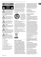
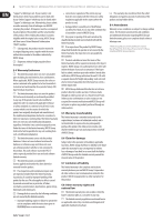
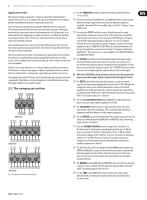
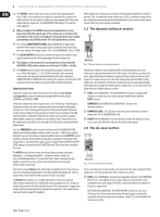
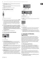
8 MULTICOM PRO-XL MDX4600/PRO-XL MDX2600/AUTOCOM PRO-XL MDX1600 User Manual (18) The OUTPUT control allows you to raise or lower the output signal by max. 20 dB, so as to make up for a gain loss caused by the compressor or limiter action. Raise the gain by roughly the same amount that it has been reduced by the compressor. The GAIN REDUCTION display (11) reads the value adjusted. ◊ When you adjust the LIMITER control in the peak limiter section, please note that the output gain of the compressor is set before the peak limiter. If the level is too high here, the peak limiter may respond permanently (see LIMITER control (29) in the peak limiter section). (19) The 12-digit INPUT/OUTPUT LEVEL display (MDX4600: 8-digit) reads both the level of the incoming audio signal and the level at the dynamics processor output. The range is from -30 to +18 dB (MDX4600: -24 to +18 dB). (20) The IN/OUT METER switch selects whether the gain LEDs read the input signal (switch pressed) or the output signal (switch not pressed). ◊ This display is referenced to the operating level selected with the OPERATING LEVEL switch on the rear of the unit (-10 dBV or +4 dBu). (21) The IN/OUT switch activates the corresponding channel. It provides a so-called "hard bypass", i.e. if it is OUT or the unit is not connected to the mains, the input jack will be linked directly to the output jack (COMPOSER PRO-XL MDX2600 only). Usually, this switch is used for direct A/B comparison between unprocessed and compressed/limited signals. Application hints Setting the compressor will be much easier if you first set both limiter and expander to a neutral setting by turning both threshold controls (TRIGGER and LIMITER) to OFF. Setting the compression ratio requires your "sense of hearing": Anything goes. In general, however, the ratio setting should not be too high for mix signals; instead, use 2:1 as a starting point to preserve the natural sound of the music; a ratio setting of about 4:1 has proved successful for vocal recordings. The IKA (Interactive Knee Adaptation) characteristic allows you to achieve a gradual and inaudible compression and hence to use higher ratios. If you want to use the compressor as an effect in its own right, don't hesitate to experiment with higher values. Turn the THRESHOLD control counter-clockwise until the GAIN REDUCTION display reads the desired gain reduction (don't exceed 6 - 8 dB for mix signals). During this process the volume is reduced audibly. Now turn the OUTPUT control clockwise until this volume difference has been made up for. The levels of the compressed vs. uncompressed signals can be compared with the INPUT/OUTPUT LEVEL display activated with the I/O METER switch. These two levels should be the same. The AUTO function for the attack and release times provides a programdependent-and largely inaudible-dynamics control, which suits most standard applications. If a somewhat more "open" sound processing profile is required, you can set the attack and release times manually (AUTO switch not pressed). Start with a longer Release time, then make it gradually shorter. You will soon notice an unnatural pumping effect caused by rapidly changing levels. Select a longer release time until the effect cannot be heard any longer. The Attack time setting, too, is highly dependent on the music material. Select longer attack times for a subtle and musical compression. As a result you avoid attack portions of treble signals being cut off if compression is triggered by a high-level bass drum beat that is played at the same time. The sound remains transparent and compact throughout. If the compressor is being used as a limiter, the attack time should be as short as possible. This, in combination with a high ratio (>20:1), a medium to long release time and the maximum possible threshold will protect your sound reinforcement system effectively from getting overloaded. 2.3 The dynamic enhancer section (23) (22) (24) MDX1600 Fig. 2.4: Dynamic enhancer section control elements The dynamic enhancer circuit implemented in all three dynamic processors allows you to dynamically enhance the treble range. Since the bass portions of a music signal often have the highest energy yield, they usually are the ones that trigger the compression process, thus also reducing the gain of middle to high frequencies. The enhancer controls the compression process and gradually adds more highs, the stronger the treble range is compressed, so as to make up for the subjective loss of high-frequency content. (22) LEVEL control (MDX1600). The AUTOCOM PRO-XL features an adjustable enhancer, on which you can set the amount of treble boost with the LEVEL control. ENHANCER switch (MDX2600 and MDX4600). Activates the dynamic enhancer. (23) ENHANCER LEVEL. The LED chain reads the current treble boost within a range from -30 to 0 dB (MDX1600 only). (24) IN/OUT switch (MDX1600). Use this switch to activate the enhancer circuit, e.g. to assess the effect the enhancer has on the audio signal. 2.4 The de-esser section (27) (26) (25) (28) MDX2600 Fig. 2.5: De-esser section control elements From a circuitry point of view, the de-esser is placed in the side-chain path of the compressor, so it will operate only if the compressor is active. (25) LEVEL control (MDX2600). Instead of an adjustable enhancer, the COMPOSER PRO-XL has a controllable de-esser, which helps you eliminate hiss noise contained in the audio signal. The LEVEL control determines the amount of frequency suppression. DE-ESSER switch (MDX1600). The AUTOCOM PRO‑XL also has a de-esser. At the touch of a button you can enhance the audio signal considerably, especially when processing vocal recordings. Switch (25) can be found in the compressor section.
-
 1
1 -
2
-
 3
3 -
 4
4 -
 5
5 -
 6
6 -
 7
7 -
 8
8 -
 9
9 -
 10
10 -
 11
11 -
 12
12 -
 13
13 -
14
-
15
 |
 |