Behringer EURODESK SX4882 Manual - Page 20
Start-up, A-channel setting up procedure, Desk/tape setting up procedures
 |
View all Behringer EURODESK SX4882 manuals
Add to My Manuals
Save this manual to your list of manuals |
Page 20 highlights
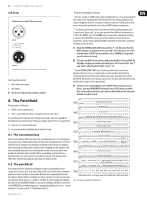
20 EURODESK SX4882 User Manual It is positively undesirable to use screened cable to wire an amp to a speaker. Speaker leads should be as thick and short as possible, with XLR or wound post terminals.) Line-level signals can usually be run unbalanced over short or moderate distances (rack to desk etc.), but NOT from the back of the hall to the stage, always provided that there are no earth loops (see section 8.3 "Looming problems" A loop acts as an aerial, positively inviting electromagnetic radiation to flow around the system). Microphone lines, however, are another story altogether. Most microphones generate not volts, but millivolts. Protecting such a low level signal requires a more sophisticated solution. Hence, all mic networks run along balanced lines. It works like this. The mic diaphragm moves forwards and backwards according to the air pressure increases and decreases that constitute sound waves. Diaphragm movement generates a corresponding electrical signal, which is either positive or negative depending on the direction of travel. The +ve and -ve signals are mirror images of each other: if you shorted + and you'd end up with nothing: one would cancel out the other. In fact this cancelling effect is what makes the balanced line work. Instead of simply shorting the negative line to earth, as would be the case in an unbalanced system (losing half the signal, or 6 dB, in the process), the two lines are kept apart until they reach an electronic (or transformer) balanced input. Here something exquisitely simple happens: You may not know this, but whenever a signal is amplified, its polarity is reversed. By inverting the negative side and adding it 1:1 to an unchanged positive, a balanced input wastes none of the available signal energy. In doing so, it also subtracts all the radiation picked up along the line. Random noise is unaffected, but you'll hear no hum, and much reduced thyristor noise (from poorly-screened lighting dimmers). Live, you could not run a rig without balanced mic lines, and although in the studio cable runs are shorter, the recorded medium's demand on signal to noise is far greater. When patching a balanced input/output to an unbalanced one, simply short the -ve and screen together at the unbalanced input or output. 13.1.2 Initializing channel for gain-setting 1) Set GAIN ( P 2 ) and all aux sends ( P 12 , P 13 , P 14 and P 15 ) to OFF (fully counterclockwise). 2) EQ switch ( S 10 ) UP (off). 3) LOW CUT switch ( S 11 ) ON for microphones, OFF for signals with desired low frequency content. 4) CHANNEL MODE set to PFL ( S 95 UP). 5) Channel PFL/SOLO ( S 26 ) switch UP ( L 26 off). 6) Check that main PFL/SOLO LED ( L 95 ) is not lit. 7) Channel PFL/SOLO switch ( S 26 ) DOWN ( L 26 and L 95 should light). 13.1.3 Auditioning a signal 1) Make a typical noise, or roll the tape. The -20 dB light should flicker, showing that a signal is present. There should also be some activity at the MAIN MIX bargraph meters, indicating the SOLOed level. 2) For LINE INPUTS: Adjust GAIN control ( P 2 ) until transient peaks are regularly hitting 0 dB. 3) For MIC INPUTS: If your meters are reading 0 dB although the GAIN control is completely turned counterclockwise, push the PAD switch ( S 1a ) to lower the input signal by 20 dB before you continue the gain adjustment. 4) TAPE inputs do not pass through the GAIN pot ( P 2 ). This is why it is important to match the operating level of the desk (-10 dBV or +4 dBu) to that of your machine. If the signal is low (due to incorrect operating level setting or too low a level having been recorded to tape), try the -10 dBV setting. If too high, try +4 dBu. If neither gives a good level, try patching the tape track output into a line input and repeat steps 13.1.1 and 13.1.2. 5) lf EQ is used, repeat steps 13.1.1 & 13.1.2. 6) If an insert is used to patch in a compressor, gate, EQ, etc., use any outboard processor's BYPASS or EFFECT OFF switch to A/B monitor the effect. Adjust the processor's output level so that effected and bypassed signals are level matched. 7) Channel PFL/SOLO switch ( S 26 ) UP. Move onto next channel. 13.2 Desk/tape setting up procedures Fig. 12.1: A balanced microphone line 13. Start-up 13.1 A-channel setting up procedure 13.1.1 Selecting inputs • MICROPHONE: MIC/LINE switch ( S 1 ) UP, PAD switch ( S 1a ) UP, FLIP switch ( S 3 ) UP • LINE: MIC/LINE switch DOWN, FLIP switch UP • TAPE: FLIP switch DOWN 13.2.1 Desk normalization All board settings should be set to the normal default condition before or after every session. Usually faders are set to zero (minus infinity), EQs set flat and switched out, trimpots and channel aux sends turned fully anticlockwise etc. The natural initial setting for some pots, e.g. master aux sends, is unity gain. However, some settings, such as selecting PRE or POST for channel aux sends and whether TAPE or MIC/LINE is flipped onto B-channel etc. will depend on the operating environment, whether in a MIDI or A/V suite, 24-track studio or live venue, or even just on the engineer's preferred way of working. Ultimately, the object of the excercise is: 13.2.2 Multitrack initialization Set up the multitrack so that any track in "record ready" condition has its input monitored when the tape is stationary. Place all tracks to be recorded into "record ready" status (once a recording has been made, these tracks should automatically switch to tape playback). Check that the input levels to each TRACK are optimized before recording commences. behringer.com
-
 1
1 -
2
-
3
-
4
-
5
-
6
-
7
-
8
-
9
-
10
-
11
-
12
-
13
-
14
-
 15
15 -
 16
16 -
 17
17 -
 18
18 -
 19
19 -
 20
20 -
 21
21 -
 22
22 -
 23
23 -
 24
24 -
 25
25 -
26
-
27
-
28
-
29
-
30
-
31
-
32
 |
 |
