Behringer EURODESK SX4882 Manual - Page 7
Input gain setting, Main equalizer, Aux sends, Routing and muting, fader - console
 |
View all Behringer EURODESK SX4882 manuals
Add to My Manuals
Save this manual to your list of manuals |
Page 7 highlights
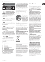
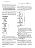
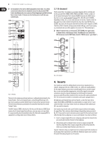
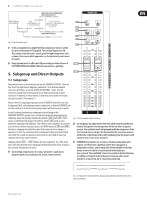
7 EURODESK SX4882 User Manual 3.3 Input gain setting The channel input level is set by the TRIMPOT ( P 2 ). Use SOLO/PFL ( S 26 ) to bring the channel's input onto the L/R bargraph meters under the master section of the EURODESK SX4882. This also sends the SOLO/PFLed signal to the left and right speakers. Channel PFL/SOLO ( S 26 ) has an associated LED ( L 26 ). (See also 13.1 "A-channel setting up procedure" and 6.5 "PFL/SOLO".) ◊ For level-setting (as opposed to localized listening) choose to use the mono PFL rather than the post fader SOLO bus ( S 95 DOWN). ◊ SOLO/PFL never interrupts the mix at the main recording outputs. It follows that aux sends and subgroups must also be unaffected, since they can contribute directly to the main mix. Thirdly, there is a steep high pass (low cut) filter ( S 11 ), slope @ 12 dB/octave, -3 dB @ 75 Hz, for reducing floor rumble, plosives, woolly bottom end, etc. 3.5 Aux sends All six aux sends are mono and post EQ. They are switchable PRE/POST fader in two banks ( S 13 and S 16 ). For aux sends 1 and 2, two dedicated pots ( P 12 and P 13 ) are used. These can be taken from a point before or after the channel fader, i.e. PRE or POST ( S 13 ). Aux sends 3 and 4, and 5 and 6 are serviced by two potentiometers ( P 14 and P 15 ). The SHIFT button ( S 15 ) determines whether buses 3 and 4 or 5 and 6 are addressed. Also, these four sends can be derived from the main mix or MIX-B, depending on SOURCE ( S 17 ), and, as before, can be pre or post ( S 16 ). In addition to switchable PFL/SOLO metering, a couple of LEDs ( L 24 and L 25 ) continuously monitor whether a signal is present (-20 dB) or the channel is going into overload (PEAK). These take their cue from three test points: input, post EQ and post fader. In all cases the higher level wins. You do NOT want the overload light to come on, or if it does no more than very intermittently during a take or a mix. 3.4 Main equalizer Fig. 3.4: Aux sends Fig. 3.3: Main equalizer The main equalizer can be switched ( S 10 ) out of circuit for easy A/B comparisons between EQed and straight signals, or when you know that you don't want to use desk EQ at all. It is best considered in three sections. First, there are two Baxendall shelving frequency controls for treble and bass, at 12 kHz and 80 Hz respectively ( P 4 and P 9 ). These are DUPLICATED for the B-channel ( P 18 and P 19 ), not merely "SPLIT" off from the main EQ. I.e. you can have a full 4-band EQ on the main channel AND a 2-band EQ on B-channel. Secondly, there are two semi-parametric swept mids, Q fixed at 1, which cover the bands 300 Hz to 20 kHz and 50 Hz to 3 kHz. An unusually broad frequency range is catered for, and there is an enormous 3-plus octave overlap between the two mid bands ( P 5 , P 6 , P 7 and P 8 ). No experienced engineer will complain about that! All four bands offer 15 dB of cut and boost. ◊ For almost all FX SEND purposes, you will want auxes to be post fader, so that when a fader level is adjusted, any reverb send from that channel follows the fader. Otherwise, when the fader is pulled down, the reverb from that channel would still be audible. For CUEing purposes, aux sends will usually be set pre fader, i.e. independent of the channel fader ( S 13 and S 16 ). ◊ Most reverbs etc. sum up the left and right inputs internally. The very few that don't may be driven in true stereo either by 1) 2 aux sends or 2) the MIX-B bus (see section 3.7 "B-channel"). ◊ There is +15 dB of gain on every aux send. Such a high boost is only appropriate where the channel fader is set around -15 dB or lower. Here, an almost exclusively WET signal will be heard. Previously, in most consoles, such a wet mix required the use of a PRE setting for the channel auxiliary send. This meant losing fader control over the signal. 3.6 Routing and muting ROUTING means selecting which BUS you want a channel to address. There are actually six stereo buses in the EURODESK SX4882 (plus a stereo SOLO bus). The main mix bus is selected by S 32 (see figure 3.5), while the subgroups are selected by switches S 28 (for groups 1 and 2), S 29 (3 and 4), S 30 (5 and 6) and S 31 (7 and 8). Odd and even numbered groups are selected via the main A-channel PAN P 24 , as are the left and right mix buses. (The sixth stereo bus is the MIX-B bus, with it's own independent pan control P 20 ; see section 3.7 "B-channel"). Usually, only one of S 28 to S 31 will be selected for a particular channel (See block schematics). behringer.com
-
 1
1 -
 2
2 -
 3
3 -
 4
4 -
 5
5 -
 6
6 -
 7
7 -
 8
8 -
 9
9 -
 10
10 -
 11
11 -
 12
12 -
13
-
14
-
15
-
16
-
17
-
18
-
19
-
20
-
21
-
22
-
23
-
24
-
25
-
26
-
27
-
28
-
29
-
30
-
31
-
32
 |
 |