Behringer FEEDBACK DESTROYER PRO DSP1124P Manual - Page 11
Feedback Destroyer Pro Dsp1124p
 |
View all Behringer FEEDBACK DESTROYER PRO DSP1124P manuals
Add to My Manuals
Save this manual to your list of manuals |
Page 11 highlights
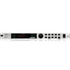
FEEDBACK DESTROYER PRO DSP1124P s A filter has been “set”, i.e. it is already suppressing feedback; or: s A filter is set to Parametric EQ mode (gain ¹ 0 dB). Cyclically flashing LEDs signal that a filter is searching feedback frequencies in Single-Shot or Auto mode (see chapters 5 and 6.3). Inactive filters (“OF”) and filters in Parametric EQ mode (see 6.2), with a gain setting of 0 dB, are indicated by unlit LEDs. 3 The LED DISPLAY consists of a clearly visible, two-digit numeric display. After power-up, it reads the number of the last preset used. Additionally, the LED-DISPLAY shows the absolute values of the parameters that are being edited. 4 The INDICATORS to the right of the DISPLAY (Hz, kHz, 1/60 and dB) light up when you edit the associated parameters in Edit mode. For example, when you raise the level of a filter, the “dB” indicator lights up. Fig. 4.2: Function keys and JOG WHEEL 5 With the JOG WHEEL, a continuous rotary control, you can freely edit the selected parameters. Turn the wheel clockwise to increase the values, or counterclockwise to reduce them. 6 With the FILTER SELECT key activated, you can use the JOG WHEEL to select one of the 12 filters per channel. Subsequently, you can edit the filters. 7 The FILTER MODE key gives you access to the four operating modes for the individual filters: “Off mode (OF)”, “Parametric EQ (PA)”, “Single-Shot mode (SI)” and “Auto mode (AU)”. Please read chapter 6 “OPERATING MODES OF THE DSP1124P”. + Pressing the FILTER MODE and GAIN keys simultaneously allows you to adjust the sensitivity of the feedback suppression trigger circuit. The setting range is from -3 through -9 dB and can be adjusted with the JOG WHEEL. The default value is -6 dB, as this setting usually delivers the best results. 8 Use the ENGINE L key to select the left audio channel. 9 Use the ENGINE R key to select the right audio channel. If you wish to process both channels at the same time (Couple mode), press both ENGINE keys together. In Couple mode both ENGINE LEDs light up. Whenever you edit one of the two audio channels and then switch to Couple mode, the parameters of the active channel will be copied to the other, i.e. if you press ENGINE L before ENGINE R, left will be copied to right. Items through refer to Parametric EQ mode only (see chapters 5 and 7.3). 10 Press the FREQUENCY key to select the frequency you wish to process. The adjustable frequency range is from 20 Hz through 20 kHz, which are split up by the DSP1124P into the 31 standard ISO values of a graphic equalizer (see chapter 11.1 in the appendix). 11 The FINE key allows you to fine tune the standard ISO frequencies (in 1/60-octave steps), within a tuning range of 1/3 octave (-9/60 to +10/60). 12 BANDWIDTH determines the filter bandwidth (Q factor) of the selected filter. This adjustable filter quality ranges from 1/60 octave to 2 octaves (120/60 octave). 4. CONTROL ELEMENTS 11
-
 1
1 -
2
-
3
-
4
-
5
-
 6
6 -
 7
7 -
 8
8 -
 9
9 -
 10
10 -
 11
11 -
 12
12 -
 13
13 -
 14
14 -
 15
15 -
 16
16 -
17
-
18
-
19
-
20
-
21
-
22
-
23
-
24
-
25
 |
 |
