Behringer FEEDBACK DESTROYER PRO DSP1124P Manual - Page 12
Control Elements - setup
 |
View all Behringer FEEDBACK DESTROYER PRO DSP1124P manuals
Add to My Manuals
Save this manual to your list of manuals |
Page 12 highlights
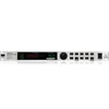
FEEDBACK DESTROYER PRO DSP1124P 13 The GAIN key sets the desired boost/cut of the selected filter in dB (+16 dB/-48 dB). 14 The IN/OUT key allows for optional bypassing of the parametric filters or all filters. By shortly pressing the IN/OUT key, only the Parametric EQ filters will be deactivated, and the green LED goes out. Hold down the key for about two seconds to deactivate all filters. This “Total Bypass” mode is indicated by the cyclic flashing of the green LED. Another short IN/OUT key press reactivates all filters. Additionally, the LED flashes when relevant MIDI data are being received. + If the control LED of the IN/OUT key flashes, all functions (including all automatic filters used for feedback suppression) are disabled (“Total Bypass”). In all other modes, at least the Single-Shot and Auto filters are active (“Bypass”). + Please use the “Total Bypass” function only with caution, because the deactivation of the filters possibly unlocks suppressed feedback. 15 Any modifications made to a preset can be stored with the STORE key, in accordance with the number shown by the DISPLAY. Ten presets are available on the DSP1124P. Press the IN/OUT and STORE keys simultaneously to enter MIDI Setup mode. 16 Use the POWER switch to switch the FEEDBACK DESTROYER PRO on or off. Fig. 4.3: Rear panel connectors and control elements 17 Use the OPERATING LEVEL switch to change from home recording level (-10 dBV) to studio level (+4 dBu), and vice versa. The level meters are adapted automatically to the selected nominal level, so that the FEEDBACK DESTROYER PRO will always work in its optimum operating range. 18 These are the balanced INPUTS of the DSP1124P, which are on 1/4" TRS and XLR connectors. 19 The two OUTPUTS of your FEEDBACK DESTROYER PRO are also on balanced 1/4" TRS and XLR connectors. 20 SERIAL NUMBER. Please take the time to fill in and return the warranty card within 14 days after the date of purchase, so as to benefit from our extended warranty. Or use our online registration option available on the World Wide Web at www.behringer.com. 21 The DSP1124P features a complete set of MIDI functions. In addition to the usual MIDI IN and MIDI OUT ports, the MIDI THRU allows you to loop through MIDI data. 22 FUSE HOLDER / VOLTAGE SELECTOR. Please make sure that your local voltage matches the voltage indicated on the unit, before you attempt to connect and operate the unit. Blown fuses may only be replaced by fuses of the same type and rating. Some models allow for inserting the fuse holder in two different positions, in order to switch over from 230-V to 115-V operation, and vice versa. Please note that for 115-V operation outside Europe, you need to use a fuse of a higher rating (see chapter 1.2). Use the enclosed power cord to connect the unit to the mains. 12 4. CONTROL ELEMENTS
-
 1
1 -
2
-
3
-
4
-
5
-
6
-
 7
7 -
 8
8 -
 9
9 -
 10
10 -
 11
11 -
 12
12 -
 13
13 -
 14
14 -
 15
15 -
 16
16 -
 17
17 -
18
-
19
-
20
-
21
-
22
-
23
-
24
-
25
 |
 |
