Behringer PMP1680S Manual - Page 8
Digital Effects Processor, Installation - powered mixer
 |
View all Behringer PMP1680S manuals
Add to My Manuals
Save this manual to your list of manuals |
Page 8 highlights
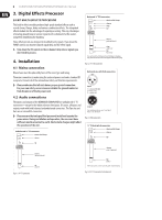
8 EUROPOWER PMP1680S/PMP980S/PMP960M User Manual 3. Digital Effects Processor 24-BIT MULTI-EFFECTS PROCESSOR This built-in effects module produces high-grade standard effects such as reverb, chorus, flanger, delay and various combination effects. The integrated effects module has the advantage of requiring no wiring. This way, the danger of creating ground loops or uneven signal levels is eliminated at the outset, completely simplifying the handling. These effect presets are designed to be added to dry signals. If you move the FX RET control, you mix the channel signal (dry) and the effect signal. ◊ Turn down the FX controls in those channel strips whose signals you don't wish to process. 4. Installation 4.1 Mains connection Blown fuses must be replaced by fuses of the same type and rating. The mains connection is made using the enclosed power cord and a standard IEC receptacle. It meets all of the international safety certification requirements. ◊ Please make sure that all units have a proper ground connection. For your own safety, never remove or disable the ground conductor from the unit or of the AC power cord. 4.2 Audio connections The inputs and outputs of the BEHRINGER EUROPOWER are unbalanced ¼" TS connectors-except for the balanced mono line inputs. Of course, all inputs and outputs work with both balanced and unbalanced connectors. The Tape Ins and Outs are on stereo RCA connectors. ◊ Please ensure that only qualified personnel install and operate the power mixer. During installation and operation, the user must have sufficient electrical contact to earth. Electrostatic charges might affect the operation of the unit. Unbalanced ¼" TS connector strain relief clamp sleeve Balanced ¼" TRS connector strain relief clamp sleeve ring tip sleeve ground/shield ring cold (-ve) tip hot (+ve) For connection of balanced and unbalanced plugs, ring and sleeve have to be bridged at the stereo plug. Fig. 4.2: ¼" TRS connector Balanced use with XLR connectors 21 3 input 1 = ground/shield 2 = hot (+ve) 3 = cold (-ve) 12 3 output For unbalanced use, pin 1 and pin 3 have to be bridged Fig. 4.3: XLR connectors ¼" TS footswitch connector strain relief clamp sleeve tip tip sleeve (ground/shield) tip (signal) sleeve pole 1/ground tip pole 2 The footswitch connects both poles momentarily Fig. 4.1: ¼" TS connector Fig. 4.4: ¼" TS connector for footswitch
-
 1
1 -
2
-
 3
3 -
 4
4 -
 5
5 -
 6
6 -
 7
7 -
 8
8 -
 9
9 -
 10
10 -
 11
11 -
 12
12 -
 13
13 -
14
-
15
 |
 |
