Behringer ULTRAGAIN PRO-8 DIGITAL ADA8000 Manual - Page 4
Introduction, Control Elements - audio interface
 |
View all Behringer ULTRAGAIN PRO-8 DIGITAL ADA8000 manuals
Add to My Manuals
Save this manual to your list of manuals |
Page 4 highlights
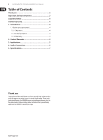
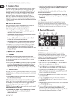
4 ULTRAGAIN PRO-8 DIGITAL ADA8000 User Manual 1. Introduction Your ADA8000 is a state-of-the art 8-channel A/D and D/A converter. This ultracompact 19" unit gives you the opportunity to connect analog audio signals directly to, say a multitrack recorder via the integrated ADAT interface. For this purpose, the ADA8000 deserves one rack space only. In return, you can even connect the digital signal of a multitracker via ADAT to the eight analog line outputs of your ADA8000. Signal conversion can be processed at 44.1 or 48 kHz with 24-bit resolution. The ADAT inputs and outputs can be operated independently as long as there is an identical wordclock signal. The integrated A/D and D/A converters ensure optimal signal conversion without any distortion or signal deterioration. IMP "Invisible" Mic Preamp The microphone channels are fitted with BEHRINGER's brand new high-end IMP INVISIBLE MIC PREAMPs that boast the following features: 130 dB dynamic range for an incredible amount of headroom, • a bandwidth ranging from below 10 Hz to over 200 kHz for crystal-clear reproduction of even the finest nuances • the extremely low-noise and distortionless circuitry guarantees absolutely natural and transparent signal reproduction • they are perfectly matched to every conceivable microphone with up to 60 dB gain and +48 volt phantom power supply and • they enable full utilisation of the greatly extended dynamic range of your 24-bit/192 kHz HD recorder, thereby maintaining optimal audio quality ◊ The following user's manual is intended to familiarize you with the unit's control elements, so that you can master all the functions. After having thoroughly read the user's manual, store it at a safe place for future reference. 1.1 Before you get started 1.1.1 Shipment The ADA8000 was carefully packed at the assembly plant to assure secure transport. Should the condition of the cardboard box suggest that damage may have taken place, please inspect the unit immediately and look for physical indications of damage. ◊ Damaged units should NEVER be sent directly to us. Please inform the dealer from whom you acquired the unit immediately as well as the transportation company from which you took delivery of the unit. Otherwise, all claims for replacement/repair may be rendered invalid. 1.1.2 Initial operation Please make sure the unit is provided with sufficient ventilation, and never place the ADA8000 on top of an amplifier or in the vicinity of a heater to avoid the risk of overheating. ◊ Before plugging the unit into a power socket, please make sure you have selected the correct voltage: The fuse compartment near the power plug socket contains three triangular markings. Two of these triangles are opposite one another. The voltage indicated adjacent to these markings is the voltage to which your unit has been set up, and can be altered by rotating the fuse compartment by 180°. ATTENTION: This does not apply to export models that were for example manufactured only for use with 120 V! ◊ If you alter the unit's voltage, you must change the fuses accordingly. The correct value of the fuses needed can be found in the chapter "Specifications". ◊ Faulty fuses must be replaced with fuses of appropriate rating without exception! The correct value of the fuses needed can be found in the chapter "Specifications". Power is delivered via the cable enclosed with the unit. All requiered safety precautions have been adhered to. ◊ Please make sure that the unit is grounded at all times. For your own protection, you should never tamper with the grounding of the cable or the unit itself. 1.1.3 Warranty Please take a few minutes and send us the completely filled out warranty card within 14 days of the date of purchase. You may also register online at behringer.com. The serial number needed for the registration is located at the top of the unit. Failure to register your product may void future warranty claims. 2. Control Elements (1) (2) (3) (6) (7) (5) (4) (8) (9) Fig. 2.1: ADA8000 channel section The ADA8000 features eight identical channels. Each section comprises a microphone input (on a balanced XLR connector) and a line-level input (on a balanced ¼" TRS jack). We recommend connecting only one input signal per channel. When two input signals are connected, the weaker signal is suppressed and will be audible as interference noise. (1) The SIG LED lights up when a signal is present at one of the inputs. (2) If the input level is too high, the CLIP LED lights up. The CLIP LED should light up only with signal peaks but never all the time. (3) Use the GAIN control to set the input gain. The gain ranges from +10 to +60 dB. The GAIN control governs both the LINE IN and the MIC IN input. (4) This is the balanced ¼" TRS LINE IN connector. A connected analog LINE IN or MIC IN signal is not routed to the analog LINE OUT connector (16). Instead, it will reach the ADAT OUT interface. (5) This is the balanced MIC IN XLR connector. For example, you can connect your microphone here. (6) As long as the ADA8000 functions as master, sending a clock signal, the SYNC MASTER LED lights up. The appropriate setting can be made on the rear (see (15)). (7) When the ADA8000 is synchronized externally (either ADAT or wordclock IN), the SYNC LOCKED-LED lights up. (8) Press the +48 V switch to provide condenser microphones which are connected to the MIC IN inputs with the required phantom power. Dynamic microphones do not require this external power supply. When the switch is depressed, phantom power is active on all inputs.
-
 1
1 -
 2
2 -
 3
3 -
 4
4 -
 5
5 -
 6
6 -
 7
7 -
 8
8 -
 9
9
 |
 |