Behringer ULTRAGAIN PRO-8 DIGITAL ADA8000 Manual - Page 6
ULTRAGAIN PRO-8 DIGITAL ADA8000 User Manual - ultragain digital
 |
View all Behringer ULTRAGAIN PRO-8 DIGITAL ADA8000 manuals
Add to My Manuals
Save this manual to your list of manuals |
Page 6 highlights
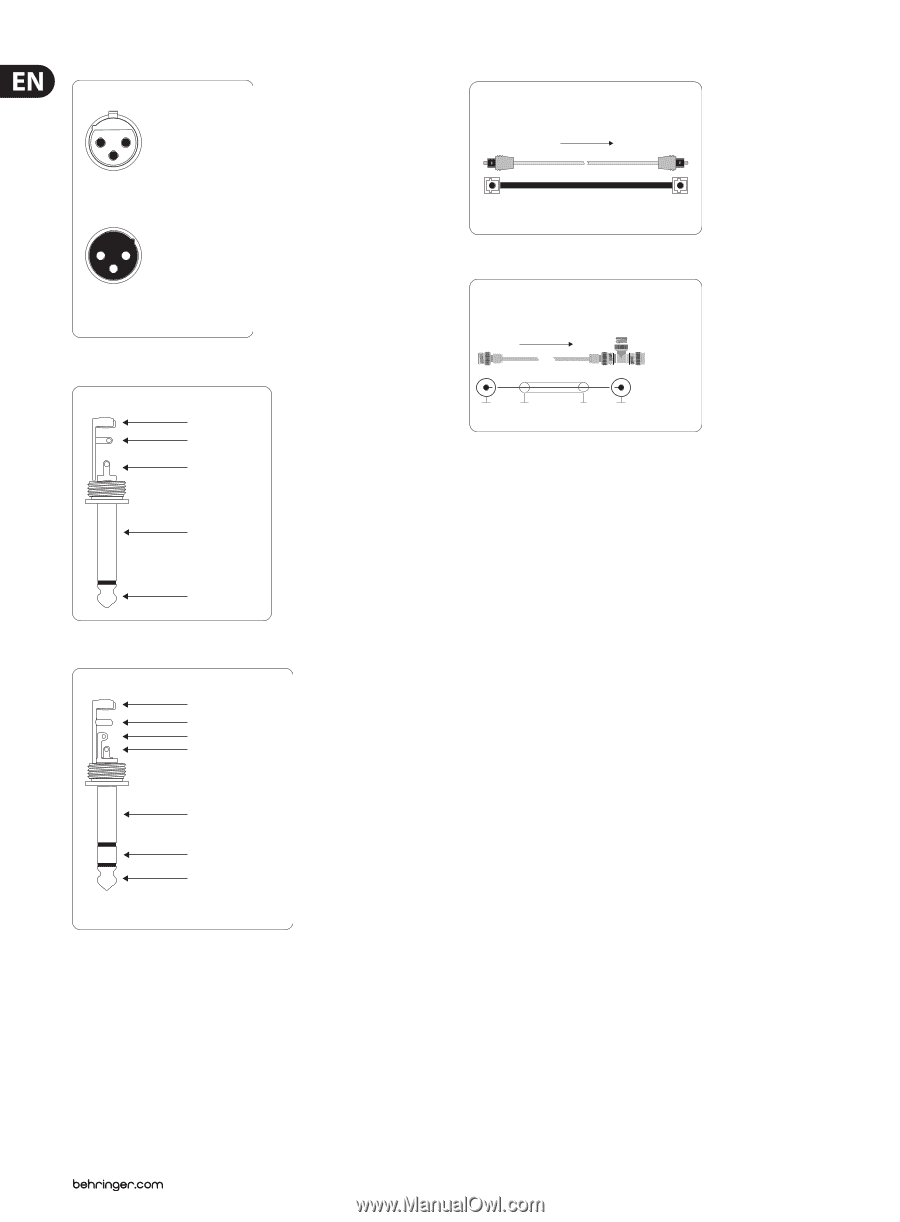
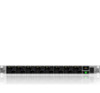
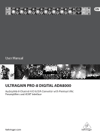
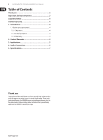
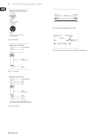
6 ULTRAGAIN PRO-8 DIGITAL ADA8000 User Manual Balanced use with XLR connectors 21 3 input 1 = ground/shield 2 = hot (+ve) 3 = cold (-ve) 12 3 output For unbalanced use, pin 1 and pin 3 have to be bridged Fig. 4.1: XLR connectors Unbalanced ¼" TS connector strain relief clamp sleeve tip sleeve (ground/shield) tip (signal) Fig. 4.2: ¼" TS connector Balanced ¼" TRS connector strain relief clamp sleeve ring tip sleeve ground/shield ring cold (-ve) tip hot (+ve) For connection of balanced and unbalanced plugs, ring and sleeve have to be bridged at the stereo plug. Fig. 4.3: ¼" TRS connector Device A ADA8000 optical in/output signal ow optical in/output Fig. 4.4: Connecting the ADA8000 optically via Toslink Wordclock output Wordclock input device A ADA8000 signal ow terminating resistor Fig. 4.5: Unbalanced connection (termination) of the ADA8000's wordclock input
-
 1
1 -
 2
2 -
 3
3 -
 4
4 -
 5
5 -
 6
6 -
 7
7 -
 8
8 -
 9
9
 |
 |