Behringer ULTRALINK UL2000M Manual - Page 7
COLOR CODE, ANTENNA, Fig. 2.2: Closeup of the ULR2000, RF LEVEL, Alphanumeric display, CHANNEL,
 |
View all Behringer ULTRALINK UL2000M manuals
Add to My Manuals
Save this manual to your list of manuals |
Page 7 highlights
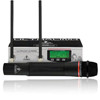
ULTRALINK UL2000M COLOR CODE Each BEHRINGER ULTRALINK transmitter can be color-coded using a color ring; this way you can easily differentiate between multiple transmitters (set to different frequencies). To easily match a transmitter to a receiver, you can also attach color-coded strips to each receiver. ANTENNA Two bar antennae can be connected to the ANTENNA 1 and ANTENNA 2 connectors. 2.1.2 Display Fig. 2.2: Closeup of the ULR2000 display (antenna symbol) These two antenna symbols indicate which antenna signal is currently being processed. The left symbol lights up when the signal from the left-hand antenna (ANTENNA 1) is stronger, and the right symbol shows that the signal from the right-hand antenna (ANTENNA 2) is being processed. RF LEVEL The 8-level RF LEVEL display shows the reception strength of the carrier frequency (Radio Frequency) on the ULR2000. If not a single bar is shown, the carrier frequency is not being received. Bad reception is indicated with 1 - 3 bars; signal noise may be somewhat higher in this case. The more bars are shown, the better the reception of the transmitter carrier frequency on the ULR2000. AF Similar to a distortion gauge on a mixer or an amplifier, the 8-level AF indicator shows how loud the demodulated audio signal (Audio Frequency) is. If the signal has no amplitude or if the amplitude is low, no bars are shown. The maximum undistorted AF-level is received when 7 bars (and not 8!) light up. Only when the audio signal is overdriving or when no RF signal can be received (the receiver creates too much noise), 8 bars are shown in the LCD. Alphanumeric display All the values and letters relevant to the operation of your ULR2000 are shown in the 6-digit alphanumeric display: for example, channel number, channel color, frequency and menu items. CHANNEL If the ULR2000 is in the basic setting (menu not selected), pressing the UP and DOWN buttons changes the transmission channel within the selected preset. If CHANNEL is lit, the individual channel numbers are shown (CHAN1, CHAN2, ...). Also, when storing a user-selected frequency in the user preset, a channel number is entered. FREQ MHz If FREQ MHz lights up, changing the transmission channel using the also displays the frequency of the selected channel. UP and DOWN buttons If neither CHANNEL nor FREQ MHz are lit, the display is indicating the channel color (BLUE, RED, ...) of the set channel. When storing a user-selected frequency in the user preset, you will be asked to enter a channel color. 2. ULR2000 RECEIVER 7
-
 1
1 -
 2
2 -
 3
3 -
 4
4 -
 5
5 -
 6
6 -
 7
7 -
 8
8 -
 9
9 -
 10
10 -
 11
11 -
 12
12 -
13
-
14
-
15
-
16
-
17
-
18
-
19
-
20
-
21
-
22
-
23
-
24
 |
 |
