Behringer VMX1000USB Manual - Page 8
Installation
 |
View all Behringer VMX1000USB manuals
Add to My Manuals
Save this manual to your list of manuals |
Page 8 highlights
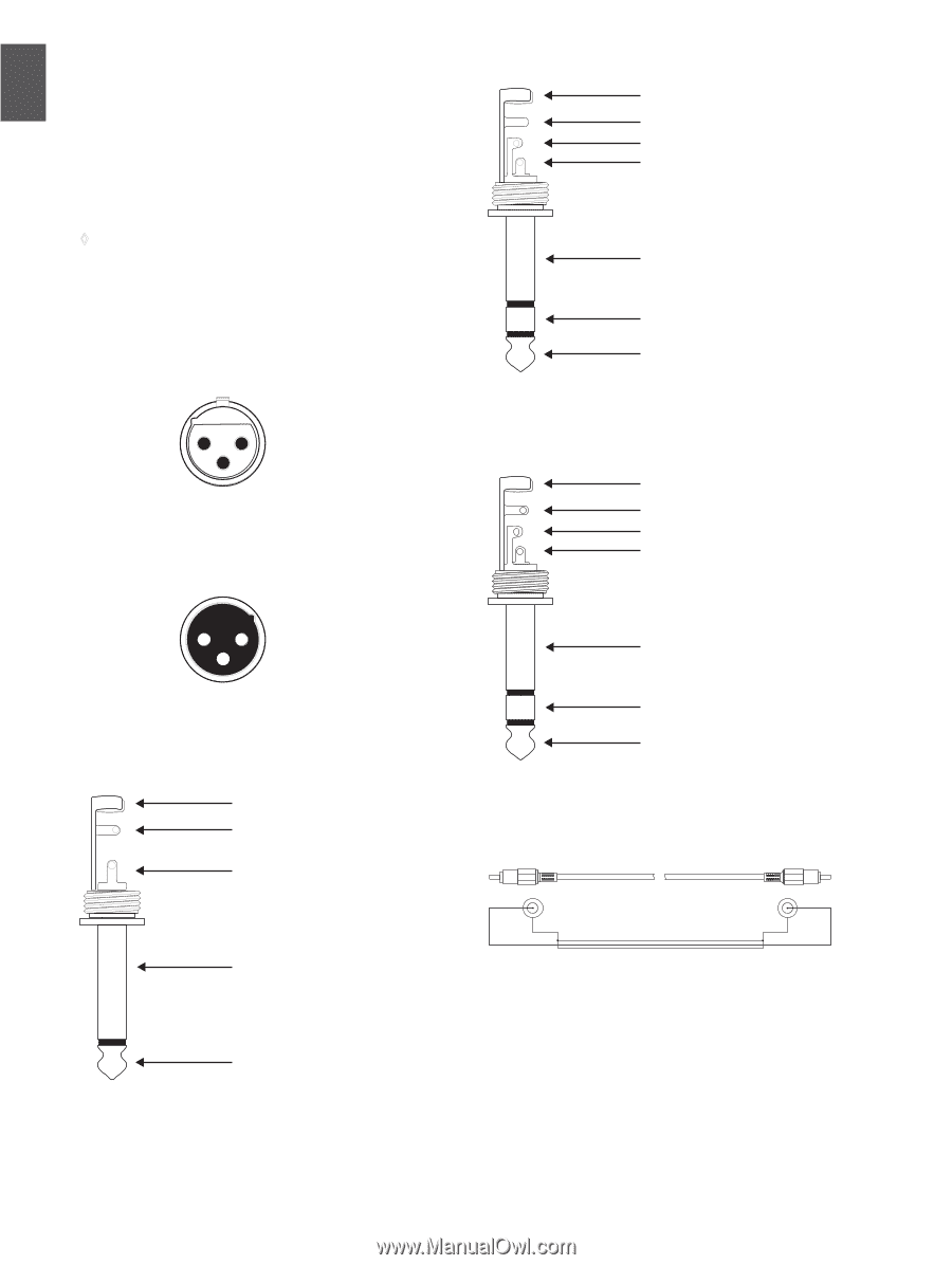
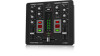
ENGLISH 8 PRO MIXER VMX1000USB User Manual 3. Installation 3.1 Audio connections for various applications, you will need a number of different cables. The following illustrations show how these cables are to be connected. Always make sure to use high-grade cables. ◊ Be sure that installation and operation of your VMX1000USB are performed only by qualified personnel. During as well as after installation, sufficient grounding of both your equipment and persons handling it must be assured. Otherwise, electrostatic discharge may lead to undesirable operation or permanent damage. input 21 3 1 = ground/shield 2 = hot (+ve) 3 = cold (-ve) strain relief clamp sleeve ring tip sleeve ground/shield ring cold (-ve) tip hot (+ve) For connection of balanced and unbalanced plugs, ring and sleeve have to be bridged at the stereo plug. Balanced 1/4" TRS connector Fig. 3.3: ¼"TRS connector strain relief clamp sleeve ring tip output 12 3 sleeve ground/shield For unbalanced use, pin 1 and pin 3 have to be bridged Balanced use with XLR connectors Fig. 3.1: XLR connections Strain relief clamp Sleeve Tip Sleeve (ground/shield) ring right signal tip left signal 1/4" TRS headphones connector Fig. 3.4: ¼" TRS headphone connector tip sleeve Fig. 3.5: RCA cable shield tip sleeve Tip (signal) Unbalanced ¼" TS connector Fig. 3.2: ¼" TS connector
-
 1
1 -
2
-
 3
3 -
 4
4 -
 5
5 -
 6
6 -
 7
7 -
 8
8 -
 9
9 -
 10
10 -
 11
11 -
 12
12 -
 13
13
 |
 |