Behringer XENYX X1222USB Manual - Page 12
Digital Effects Processor and, XPQ Surround Function - rack mount
 |
View all Behringer XENYX X1222USB manuals
Add to My Manuals
Save this manual to your list of manuals |
Page 12 highlights
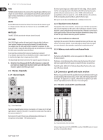
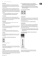
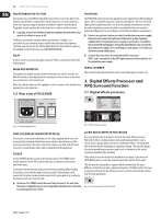
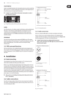
12 XENYX X1222USB User Manual FBQ FEEDBACK DETECTION The switch turns on the FBQ Feedback Detection System. It uses the LEDs in the frequency band faders to indicate the critical frequencies. On a per-need basis, lower the frequency range in question somewhat in order to avoid feedback. The graphic stereo equalizer has to be turned on in order to use this function. ◊ Logically, at least one (ideally several) microphone channels have to be open for feedback to occur at all! Feedback is particularly common when stage monitors ("wedges") are concerned, because monitors project sound in the direction of microphones. Therefore, you can also use the FBQ Feedback Detection for monitors by placing the equalizer in the monitor bus (see MAIN MIX/MONITOR). EQ IN Use this switch to activate the graphic equalizer. When activated, the fader LEDs will illuminate. MAIN MIX/MONITOR This toggles the graphic equalizer between the main mix and the monitor mix. With the switch up (not depressed), the equalizer is active in stereo on the main mix, and inactive on the monitor mix. When the switch is depressed the equalizer is active in mono on the monitor mix, and inactive on the main mix. 2.5 Rear view of X1222USB PHANTOM The PHANTOM switch activates the phantom power supply for the XLR microphone inputs, which is required to operate condenser microphones. The red +48 V LED lights up when phantom power is on. As a rule, dynamic microphones can still be used with phantom power switched on, provided that they are wired in a balanced configuration. In case of doubt, contact the microphone manufacturer! ◊ Connect microphones before you switch on the phantom power supply. Please do not connect microphones to the mixer (or the stagebox/ wallbox) while the phantom power supply is switched on. In addition, the monitor/PA loudspeakers should be muted before you activate the phantom power supply. After switching on, wait approx. one minute to allow for system stabilization. ◊ Caution! You must never use unbalanced XLR connectors (PIN 1 and 3 connected) on the MIC input connectors if you want to use the phantom power supply. SERIAL NUMBER Please note the important information on the serial number given in chapter 1.3.3. 3. Digital Effects Processor and XPQ Surround Function 3.1 Digital effects processor Fig. 2.17: Voltage supply and fuse Fig. 3.1: Effects presets overview FUSE HOLDER/IEC MAINS RECEPTACLE The console is connected to the mains via the cable supplied, which meets the required safety standards. Blown fuses must only be replaced by fuses of the same type and rating. The mains connection is made via a cable with IEC mains connector. An appropriate mains cable is supplied with the equipment. POWER Use the POWER switch to power up the mixing console. The POWER switch should always be in the "Off" position when you are about to connect your unit to the mains. To disconnect the unit from the mains, pull out the main cord plug. When installing the product, ensure that the plug is easily accessible. If mounting in a rack, ensure that the mains can be easily disconnected by a plug pull or by an all-pole disconnect switch on or near the rack. ◊ Attention: The POWER switch does not fully disconnect the unit from the mains. Unplug the power cord completely when the unit is not used for prolonged periods of time. 24-BIT MULTI-EFFECTS PROCESSOR Here you can find a list of all presets stored in the multi-effects processor. This built-in effects module produces high-grade standard effects such as reverb, chorus, flanger, delay and various combination effects. The integrated effects module has the advantage of requiring no wiring. This way, the danger of creating ground loops or uneven signal levels is eliminated at the outset, completely simplifying the handling. These effect presets are designed to be added to dry signals. If you move the FX TO MAIN control, you mix the channel signal (dry) and the effect signal. This also goes for mixing effects signals with the monitor mix. The main difference is that the mix ratio is adjusted using the FX TO MON control. Of course, a signal has to be fed into the effects processor via the FX control in the channel strip for both applications. Fig. 3.2: Connection socket for the footswitch
-
 1
1 -
2
-
3
-
4
-
5
-
6
-
 7
7 -
 8
8 -
 9
9 -
 10
10 -
 11
11 -
 12
12 -
 13
13 -
 14
14 -
 15
15 -
 16
16 -
 17
17
 |
 |
