Behringer XENYX X1222USB Manual - Page 8
Stereo channels, Connector panel and main - case
 |
View all Behringer XENYX X1222USB manuals
Add to My Manuals
Save this manual to your list of manuals |
Page 8 highlights
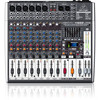
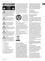
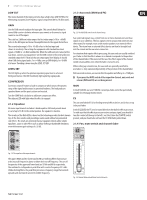
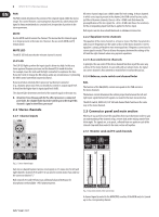
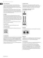
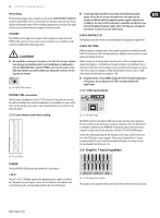
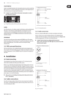
8 XENYX X1222USB User Manual PAN The PAN control determines the position of the channel signal within the stereo image. This control features a constant-power characteristic, which means the signal is always maintained at a constant level, irrespective of position in the stereo panorama. MUTE Use the MUTE switch to mute the channel. This means that the channel signal is no longer present in the main mix. However, the aux sends (MON and FX) remain active. MUTE LED The MUTE LED indicates that the relevant channel is muted. CLIP LED The CLIP LED lights up when the input signal is driven too high. In this case, lower apparent frequency increase on the channel EQ to avoid distortion. For example, lower the mids and the highs somewhat to emphasize the bass. If you don't wish to change the EQ settings under any circumstances, try lowering the GAIN control somewhat (counterclockwise). If you inserted an external effects processor via the insert connector (e.g. a dynamic processor), then you should also control its output signal level. It should not be higher than its input signal level (0 dB). The channel fader determines the level of the channel signal in the main mix. ◊ Attention: Since the aux path for the effect processor is connected post-fader, the channel fader has to be turned up in order to get this channel's signal to the effects processor! 2.2 Stereo channels 2.2.1 Channel inputs All stereo channel strips have a GAIN control for level setting. In those channels in which a mic input is present in the channel, the GAIN control has two scales: just like in the mono channels, there is a 0 to +40 dB scale that shows the preamplification of the mic signal; the +20 to -20 dB scale shows the sensitivity for the corresponding input level that is applied to the line input. Both inputs can also be used with balanced or unbalanced connectors. 2.2.2 Equalizer stereo channels The equalizer of the stereo channels is, of course, stereo. The filter characteristics and crossover frequencies are the same as those of the mono channels. A stereo equalizer is always preferable to two mono equalizers if frequency correction of a stereo signal is needed. There is often a discrepancy between the settings of the left and the right channels when using separate equalizers. 2.2.3 Aux sends stereo channels In principle, the aux sends of the stereo channels function in just the same way as those of the mono channels. As aux send paths are always mono, the signal on a stereo channel is first summed to mono before it reaches the aux bus. 2.2.4 Balance, mute switch and channel fader BAL The function of the BAL(ANCE) control corresponds to the PAN control in the mono channels. The balance control determines the relative proportion between the left and right input signals before both signals are routed to the main stereo mix bus. The MUTE switch, MUTE LED, CLIP LED and channel fader function in the same way as the mono channels. 2.3 Connector panel and main section Whereas it was useful to trace the signal flow from top to bottom in order to gain an understanding of the channel strips, we now look at the mixing console from left to right. The signals are, so to speak, collected from one point on each of the channel strips and then routed to the main section all together. 2.3.1 Monitor send and FX send channels Fig. 2.5: Stereo channel inputs Each stereo channel features two line-level inputs on ¼" connectors for left and right channels. Channels 9/10 and 11/12 can also be used in mono if you only use the connector labeled "L." Both channels 5/6 and 7/8 feature an additional balanced XLR input for microphones with available +48 V phantom power. Fig. 2.6: Aux send controls of the main section A channel signal is routed to the MON(ITOR) send bus if the MON control is turned up on the corresponding channel.
-
 1
1 -
2
-
 3
3 -
 4
4 -
 5
5 -
 6
6 -
 7
7 -
 8
8 -
 9
9 -
 10
10 -
 11
11 -
 12
12 -
 13
13 -
14
-
15
-
16
-
17
 |
 |