Belkin F1DN108U User Manual - Page 17
Step 3, Connecting Computers to the Switch
 |
UPC - 722868600825
View all Belkin F1DN108U manuals
Add to My Manuals
Save this manual to your list of manuals |
Page 17 highlights
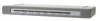
Installation Step 3 Connecting Computers to the Switch (required) 3.1 Make sure all computers and the Switch are powered off. 3.2 Using the Belkin All-In-One USB KVM Cable Kit (F3X1962bXX), connect the male VGA connector to the monitor port on your computer. Then connect the female VGA connector to the CPU monitor port on the Switch labeled "VGA 01". (Refer to diagram below.) 3.3 Using the Cable Kit, connect the USB Type A connector to an available USB port on your computer. Then connect the USB Type B connector to the USB port on the Switch labeled "USB 01". (Refer to diagram below.) 3.4 Repeat steps 2 and 3 for each additional USB computer you wish to connect. Note: The Cable Kit must be connected directly to a free USB port on your computer, with no USB hubs or other devices in between. 12
-
 1
1 -
2
-
3
-
4
-
5
-
6
-
7
-
8
-
9
-
10
-
11
-
 12
12 -
 13
13 -
 14
14 -
 15
15 -
 16
16 -
 17
17 -
 18
18 -
 19
19 -
 20
20 -
 21
21 -
 22
22 -
23
-
24
-
25
-
26
 |
 |
