Belkin PF60 AP41300-12 User Manual - Page 21
K. Bank Selector Button, L. Dimmer Button, Auxiliary Power Outlet
 |
UPC - 722868652480
View all Belkin PF60 manuals
Add to My Manuals
Save this manual to your list of manuals |
Page 21 highlights
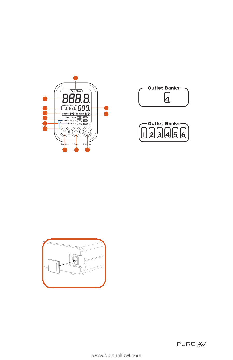
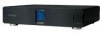
Operation K. Bank Selector Button - lets you select which outlet banks you want to monitor; press the button repeatedly to choose either a single bank (Fig. 5a) or all banks (Fig. 5b). L. Dimmer Button - adjusts the brightness of the LCD Control Panel; press it repeatedly to change the brightness level. A B D C E F Figure 5a G H I J KL Figure 5b Auxiliary Power Outlet The Power Console is equipped with a front auxiliary power outlet. This outlet contains a digital noise filter and is a convenient place to connect digital video cameras, digital still cameras, MP3 players, or any other portable device in need of AC power. Simply remove the small door covering the outlet by sliding it to the right (Fig. 6) and plug in your device. Note: The Auxiliary Power Outlet is controlled by the "Bank 01" slide switches on the rear panel of the Power Console. See page 8 for further instructions on programming the outlet banks. Figure 6 20
-
 1
1 -
2
-
3
-
4
-
5
-
6
-
7
-
8
-
9
-
10
-
11
-
12
-
13
-
14
-
15
-
 16
16 -
 17
17 -
 18
18 -
 19
19 -
 20
20 -
 21
21 -
 22
22 -
 23
23 -
 24
24 -
 25
25 -
 26
26 -
27
-
28
 |
 |