BenQ 0.6 Wall Mount-WM06G3 Wall Mount User Manual - Page 7
English
 |
View all BenQ 0.6 Wall Mount-WM06G3 manuals
Add to My Manuals
Save this manual to your list of manuals |
Page 7 highlights
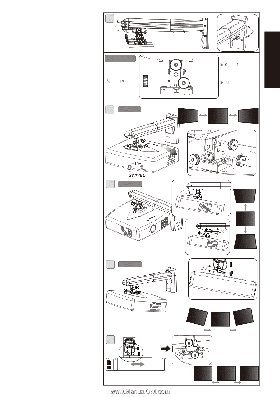
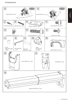
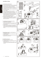
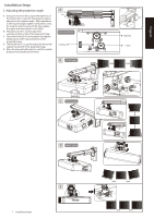
English English Installation Steps 5. Adjusting the projection angle A. Using a hex wrench (K) to adjust the tightness of the internal hex screws (H), the projector may be adjusted to the required angle. After adjustment to the required angle, tighten internal hex screws (F) using the 5mm hex wrench (K), then replace the upper and lower plastic cover (N)(O). B. The gray knob (A) is used to adjust the sideways rotation angle of the projected image. C. The yellow knob (B) is used to adjust the angular displacement of the top and bottom of the projected image. D. The black knob (C) is used to adjust the horizontal angular movement of the projected image. E. Move the base plate(A)inside the rails(B) to enable projector horizontally lateral moves. A Knob color indication Yellow B Knob A (gray) C Knob B (yellow) F H Black Gray D Knob C (black) E 7 Installation Steps A B
-
 1
1 -
 2
2 -
 3
3 -
 4
4 -
 5
5 -
 6
6 -
 7
7
 |
 |