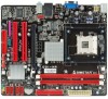
Biostar G31-M4 Setup Manual - Page 15
F_USB1/F_USB2: Headers for USB 2.0 Ports at Front Panel, F_AUDIOF1: Front Panel Audio Header
 |
View all Biostar G31-M4 manuals
Add to My Manuals
Save this manual to your list of manuals |
Page 15 highlights
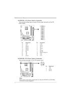
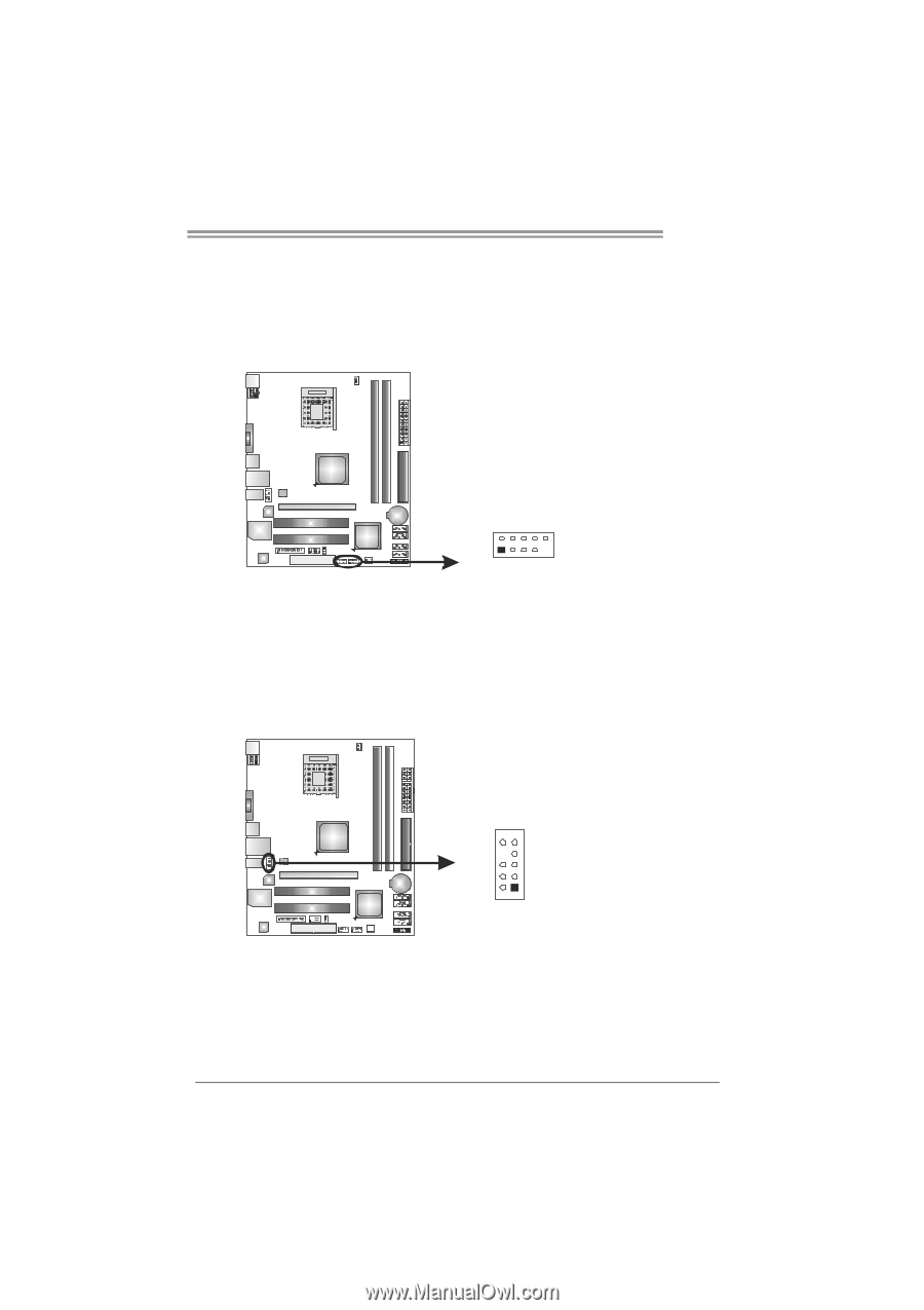
G31-M4 F_USB1/F_USB2: Headers for USB 2.0 Ports at Front Panel This motherboard provides 2 USB 2.0 headers, which allows user to connect additional USB cable on the PC front panel, and also can be connected with internal USB devices, like USB card reader. F_ USB 1 F_USB2 2 10 1 9 Pin Assignment 1 +5V (fused) 2 +5V (fused) 3 USB4 USB5 USB+ 6 USB+ 7 Ground 8 Ground 9 Key 10 NC F_AUDIOF1: Front Panel Audio Header This header allows user to connect the front audio output cable with the PC front panel. This header allows only HD audio front panel connector; AC'97 connector is not acceptable. 10 9 2 1 Pin Assignment 1 Mic Left in 2 Ground 3 Mic Right in 4 GPIO 5 Right line in 6 Jack Sense 7 Front Sense 8 Key 9 Left line in 10 Jack Sense 13
-
 1
1 -
2
-
3
-
4
-
5
-
6
-
7
-
8
-
9
-
 10
10 -
 11
11 -
 12
12 -
 13
13 -
 14
14 -
 15
15 -
 16
16 -
 17
17 -
 18
18 -
 19
19 -
 20
20 -
21
-
22
-
23
-
24
-
25
-
26
-
27
-
28
-
29
-
30
-
31
-
32
-
33
-
34
-
35
-
36
-
37
-
38
-
39
-
40
-
41
-
42
-
43
-
44
-
45
 |
 |
G31-M4
13
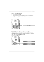
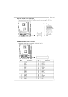
F_USB1/F_USB2: Headers for USB 2.0 Ports at Front Panel
This motherboard provides 2 USB 2.0 headers, which allows user to connect
additional USB cable on the PC front panel, and also can be connected with
internal USB devices, like USB card reader.
Pin
Assignment
1
+5V (fused)
2
+5V (fused)
3
USB-
4
USB-
5
USB+
6
USB+
7
Ground
8
Ground
9
Key
1
9
2
10
F_USB1
F_USB2
10
NC
F_AUDIOF1: Front Panel Audio Header
This header allows user to connect the front audio output cable with the PC front
panel. This header allows only HD audio front panel connector; AC’97 connector
is not acceptable.
Pin
Assignment
1
Mic Left in
2
Ground
3
Mic Right in
4
GPIO
5
Right line in
6
Jack Sense
7
Front Sense
8
Key
9
Left line in
10
Jack Sense
1
9
2
10