Biostar G31-M4 Setup Manual - Page 8
CPU_FAN1: CPU Fan Header, SYS_FAN1: System Fan Header - motherboard
 |
View all Biostar G31-M4 manuals
Add to My Manuals
Save this manual to your list of manuals |
Page 8 highlights
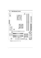
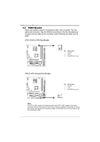
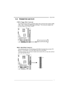
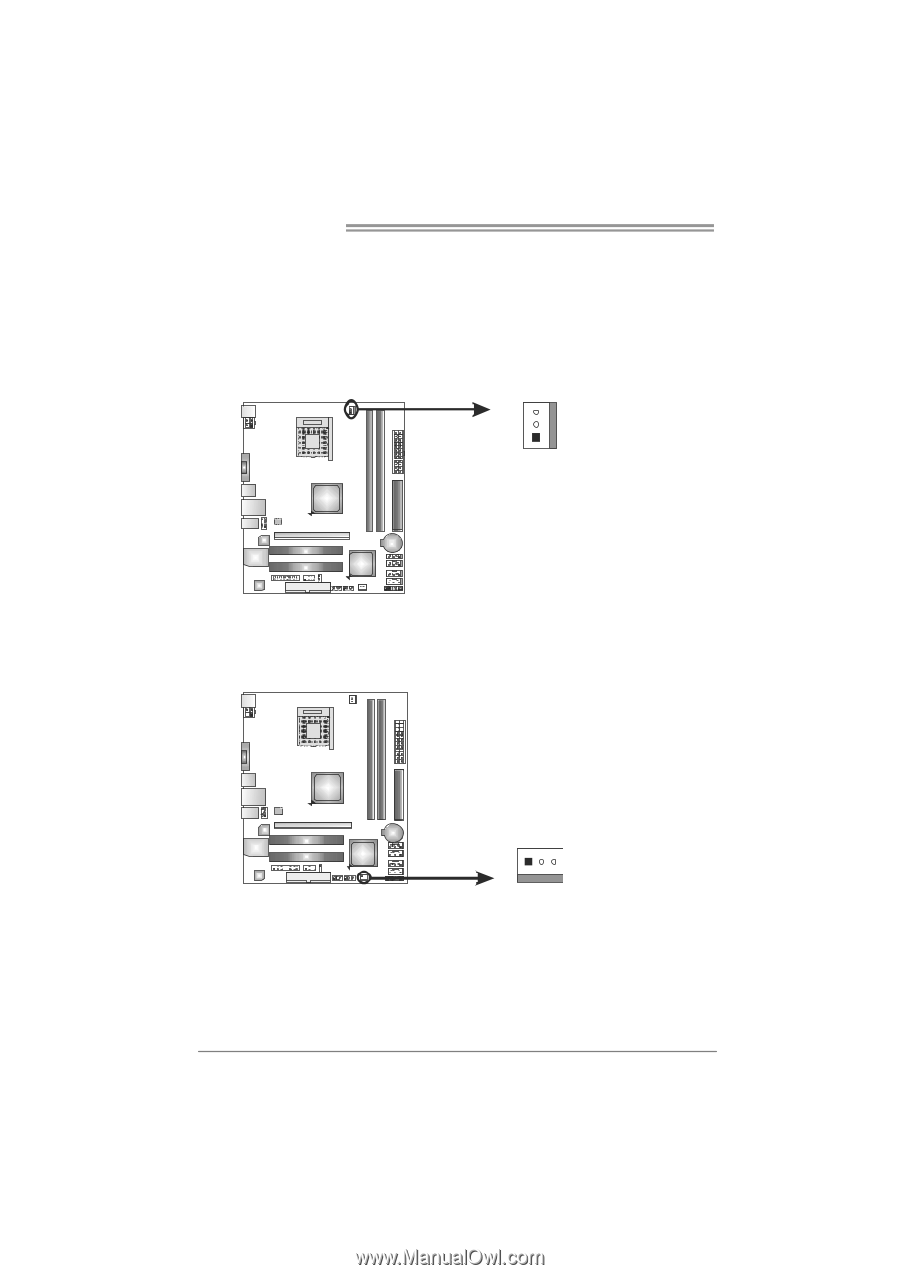
Motherboard Manual 2.2 FAN HEADERS These fan headers support cooling-fans built in the computer. The fan cable and connector may be different according to the fan manufacturer. Connect the fan cable to the connector while matching the black wire to pin#1. CPU_FAN1: CPU Fan Header 3 1 Pin Assignment 1 Ground 2 Power 3 FAN RPM rate sense SYS_FAN1: System Fan Header Pin Assignment 1 Ground 2 +12V 3 FAN RPM rate sense 13 Note: The CPU_FAN1 support 4-pin head connector and SYS_FAN1 support 3-pin head connector. When connecting with wires onto connectors, please note that the red wire is the positive and should be connected to pin#2, and the black wire is Ground and should be connected to GND. 6
-
 1
1 -
2
-
 3
3 -
 4
4 -
 5
5 -
 6
6 -
 7
7 -
 8
8 -
 9
9 -
 10
10 -
 11
11 -
 12
12 -
 13
13 -
14
-
15
-
16
-
17
-
18
-
19
-
20
-
21
-
22
-
23
-
24
-
25
-
26
-
27
-
28
-
29
-
30
-
31
-
32
-
33
-
34
-
35
-
36
-
37
-
38
-
39
-
40
-
41
-
42
-
43
-
44
-
45
 |
 |
Motherboard Manual
6
2.2
FAN
H
EADERS
These fan headers support cooling-fans built in the computer. The fan
cable and connector may be different according to the fan manufacturer.
Connect the fan cable to the connector while matching the black wire to
pin#1.
CPU_FAN1: CPU Fan Header
Pin
Assignment
1
Ground
2
Power
3
FAN RPM rate sense
1
3
SYS_FAN1: System Fan Header
Pin
Assignment
1
Ground
2
+12V
1
3
3
FAN RPM rate sense
Note:
The CPU_FAN1 support 4-pin head connector and SYS_FAN1 support 3-pin head
connector. When connecting with wires onto connectors, please note that the red wire is
the positive and should be connected to pin#2, and the black wire is Ground and should
be connected to GND.