Biostar G31D-M7 Bios Setup - Page 11
Onboard Floppy Controller, Serial Port1 Address, Parallel Port Address, Parallel Port Mode, ECP Mode - specification
 |
View all Biostar G31D-M7 manuals
Add to My Manuals
Save this manual to your list of manuals |
Page 11 highlights
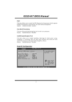
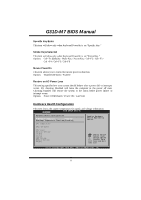
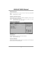
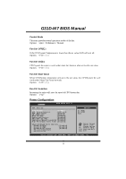
G31D-M7 BIOS Manual Onboard Floppy Controller Select enabled if your system has a floppy disk controller (FDC) installed on the system board and you wish to use it. If you installed another FDC or the system uses no floppy drive, select disabled in this field. Options: Enabled (Default) / Disabled Serial Port1 Address Select an address and corresponding interrupt fo r the first and second seri al ports. Options: 3F8/IRQ4 (Default) / 2F8/IRQ3 / 3E8/IRQ4 / 2E8/IRQ3 / Auto / Disabled Parallel Port Address T his item allows you to determine access onboard p arallel port controller with which I/O Address. Options: 378 (Default) / 278 / 3BC / Disabled Parallel Port M ode T his item allows you to determine how the parallel port should function. Options: Normal (Default) Using Parallel port as Standard Printer Port. EPP Using Parallel Port as Enhanced Parallel Port. ECP Using Parallel port as Extended Capabilities Port. ECP+EPP Using Parallel port as ECP & EPP mode. ECP Mode DMA Channel T his item allows you to select parallel port ECP DMA. Options: DMA3 (Default) / DMA0 / DMA1 Parallel Port IRQ T his item allows you to select the IRQ for the onboard parallel port. Options: IRQ7 (Default) / IRQ5 / Disabled Keyboard Pow erOn T his item allows you to control the keyboard power on function. Options: Disabled (Default) / Specific Key / Stroke Key 10
-
 1
1 -
2
-
3
-
4
-
5
-
 6
6 -
 7
7 -
 8
8 -
 9
9 -
 10
10 -
 11
11 -
 12
12 -
 13
13 -
 14
14 -
 15
15 -
 16
16 -
17
-
18
-
19
-
20
-
21
-
22
-
23
-
24
-
25
-
26
-
27
-
28
-
29
-
30
-
31
-
32
-
33
-
34
 |
 |
