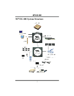
Biostar M7VIG 400 M7VIG 400 user's manual - Page 10
Installing DDR Module, Jumpers, Headers, Connectors & Slots - motherboard
 |
View all Biostar M7VIG 400 manuals
Add to My Manuals
Save this manual to your list of manuals |
Page 10 highlights
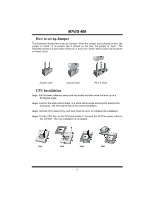
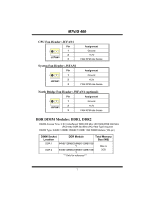
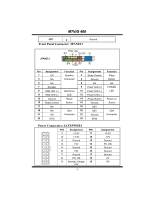
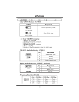
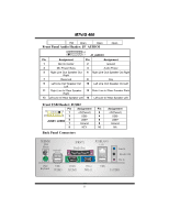
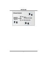
MM77VVIIGG 440000 Installing DDR Module 1. Unlock a DIMM slot by pressing the retaining clips outward. Align a DIMM to the slot in the way that the notch of the DIMM matches the break of the slot. 2. Insert the DIMM vertically and firmly into the slot until the retaining chip snap back in place and the DIMM is properly seated. Jumpers, Headers, Connectors & Slots Floppy Disk Connector: FDD1 The motherboard provides a standard floppy disk connector that supports 360K, 720K, 1.2M, 1.44M and 2.88M floppy disk types. This connector supports the provided floppy drive ribbon cables. Hard Disk Connectors: IDE1/ IDE2 The motherboard has a 32-bit Enhanced PCI IDE Controller that provides PIO Mode 0~5, Bus Master, and Ultra DMA 33/ 66/ 100/ 133 functionality. It has two HDD connectors IDE1 (primary) and IDE2 (secondary). The IDE connectors can connect a master and a slave drive, so you can connect up to four hard disk drives. The first hard drive should always be connected to IDE1. Peripheral Component Interconnect Slots: PCI 1-3 This motherboard is equipped with 3 standard PCI slots. PCI stands for Peripheral Component Interconnect, and it is a bus standard for expansion cards. This PCI slot is designated as 32 bits. Accelerated Graphics Port Slot: AGP1 Your monitor will attach directly to that video card. This motherboard supports video cards for PCI slots, but it is also equipped with an Accelerated Graphics Port (AGP). An AGP card will take advantage of AGP technology for improved video efficiency and performance, especially with 3D graphics. Communication Network Riser Slot: CNR1 (optional) The CNR specification is an open Industry Standard Architecture, and it defines a hardware scalable riser card interface, which supports modem only. Case Open Connector: JCI1 1 Pin Assignment 1 Case Open Signal 8
-
 1
1 -
2
-
3
-
4
-
 5
5 -
 6
6 -
 7
7 -
 8
8 -
 9
9 -
 10
10 -
 11
11 -
 12
12 -
 13
13 -
 14
14 -
 15
15 -
16
-
17
-
18
-
19
-
20
-
21
-
22
-
23
-
24
-
25
-
26
-
27
-
28
 |
 |