Biostar M7VIG M7VIG user's manual
Biostar M7VIG Manual
 |
View all Biostar M7VIG manuals
Add to My Manuals
Save this manual to your list of manuals |
Biostar M7VIG manual content summary:
- Biostar M7VIG | M7VIG user's manual - Page 1
M7VIG Federal Communications cable. (Can be obtained from multiple retail outlets) 3. Shielded video cable. (Can be obtained from multiple retail outlets) 4. Shielded you did not installed and used in accordance with the instructions, may cause harmful interference in the radio communications. There - Biostar M7VIG | M7VIG user's manual - Page 2
by the vendor under a license agreement. All trademarks used in this manual are property of their respective owners. Copyright© 2001 All Rights Reserved appareil numérique n'émet pas de bruits radioélectriques dépassant les limites appliquées aux appareils numériques de Class B préscrits dans le - Biostar M7VIG | M7VIG user's manual - Page 3
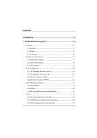
Description 1-2 1.1 Features 1-2 1.1.1 Hardware...1-2 1.1.2 Software...1-6 1.1.3 Accessories ...1-6 1.2 Motherboard Installation 1-7 1.2.1 System Block Diagram 1-7 1.2.2 Layout of Motherboard 1-8 1.2.3 Quick Reference 1-9 1.3 CPU Installation 1-10 1.3.1 CPU Installation Procedure: Socket - Biostar M7VIG | M7VIG user's manual - Page 4
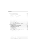
Interface port: COM1 1-28 1.7.3.2 Video Graphics Adapter Port: JVGA1 1-30 1.7.3.3 Parallel Interface Port: JPRNT1 1-31 1.7.4 Game and Audio Port Connector: AUD_GAME1 1-32 1.7.5 Audio Subsystem 1-33 1.7.5.1 CD-ROM Audio-In Connector: JCDIN1 1-34 1.7.5.2 CD-ROM Audio-In Connector: JCDIN2 1-34 - Biostar M7VIG | M7VIG user's manual - Page 5
Contents 1.7.5.4 Telephony Audio Connector: JTAD1 1-34 2. BIOS Setup 2-1 2.1 Main Menu 2-3 2.2 Standard CMOS Features 2-6 2.3 Advanced BIOS Features 2-9 2.4 Advanced Chipset Features 2-13 2.5 Integrated Peripherals 2-18 2.6 Power Management Setup 2-23 2.7 PnP/PCI Configurations 2-28 2.8 PC - Biostar M7VIG | M7VIG user's manual - Page 6
. In the tradition of its predecessors, this motherboard continues the commitment of reliability, performance and strives keyboard port, audio ports, USB ports, a LAN port and a game port. 8 Contains on board IDE facilities for IDE devices such as hard disks and CD-ROM Drives. 8 Supports the AMD - Biostar M7VIG | M7VIG user's manual - Page 7
(FSB). Chipset − Chipset - VIA KM266/ VT8233A. − Chipset - LAN Chip Realtek RTL 8100B (Optional). Speed − Supports up to AMD Athlon TM XP 2100 memory controller provide shadow RAM and supports for ROM BIOS. Green Function − Support power management operation via BIOS. − Power down timer from 1 - Biostar M7VIG | M7VIG user's manual - Page 8
Motherboard Description − Wakes from power saving sleep mode at the press of any key or any mouse activity. BUS Slots − Three 32-bit PCI bus master slots. − One CNR slot. − One AGP slot. Flash Memory − Supports flash memory. − Supports 3D Graphics Controller and Video Accelerator − Optimized Shared - Biostar M7VIG | M7VIG user's manual - Page 9
high capacity hard disk drives. − Supports LBA mode. Stereo AC 97 Digital Audio Codec − AC 97 2.1 interface. − 16 channels of high-quality sample rate conversion. − 16x8 channel digital mixer. − Stereo 10 band graphic equalizer. − Sound Blaster® and Sound Blaster Pro® emulation. − 64-voice wavetable - Biostar M7VIG | M7VIG user's manual - Page 10
Capabilities Port (ECP). (4) Normal. − Supports two serial ports, 16550 UART. − Supports one Infrared transmission (IR). − Supports PS/2 mouse and PS/2 keyboard. − Supports 360KB, 720KB, 1.2MB, 1.44MB, and 2.88MB floppy disk drivers. Universal Serial Bus − Supports two back Universal Serial Bus (USB - Biostar M7VIG | M7VIG user's manual - Page 11
Chapter 1 Motherboard Description 1.1.2 Software BIOS AWARD legal BIOS. Supports APM1.2. Supports USB Function. Supports ACPI. Operating System − − Flash Memory Writer for BIOS Update. − USB2 Cable (Optional). − Rear I/O Panel for Micro ATX Case (Optional). − Fully Setup Driver CD. 1-6 - Biostar M7VIG | M7VIG user's manual - Page 12
Chapter 1 Motherboard Description 1.2 Motherboard Installation DE I DE US B US B LPC BIOS MOUSE KEYBOARD WINBOND W83697HF FLOPPY LPT. CONN. CONN. M7VIG Micro ATX(FSB: 133/100MHz) SUPPORTS 4 DIMMS SUPPORT 1 AGP SLOT SER. CONN. SUPPORTS 3 PCI SLOTS SER. SUPPORT TELEPHONY CONN. SUPPORT - Biostar M7VIG | M7VIG user's manual - Page 13
Description 1.2.2 Layout of Motherboard Model No. M7VIG JKBMS1 JATXPWR1 JUSBLAN1 JCOM1 JPRNT1 JCFAN1 1 GAME Port DDR1 DDR2 SDR1 SDR2 JVGA1 JSPKR1 SP-OUT JLIN1 LINE-IN JMIC1 MIC-IN JAUD GAME LAN - Biostar M7VIG | M7VIG user's manual - Page 14
1 Motherboard Description 1.2.3 Quick Reference I HG F E D C B A V U LAN CHIP T J K Winbond 83679HF L M VT8233A PRIMARY IDE CONN. SECONDARY IDE CONN. FLOPPY DISK CONN. N O P A. Back Panel Connectors B. AGP Slot (AGP1) C. Front Audio Header (JAUDIO1) D. PCI BUS Slots (PCI1-3) E. CD Audio - Biostar M7VIG | M7VIG user's manual - Page 15
Chapter 1 Motherboard Description 1.3 CPU Installation 1.3.1 CPU Installation Procedure: Socket A CPU 1. Pull the lever sideways away from the socket then raise the lever up to a 90-degree angle. 2. - Biostar M7VIG | M7VIG user's manual - Page 16
Chapter 1 Motherboard Description JCFAN1 1 DDR1 DDR2 SDR1 SDR2 LAN CHIP KM 266 BAT1 VT8233A Winbond 83679HF PRIMARY IDE CONN. SECONDARY IDE CONN. FLOPPY DISK CONN. 1 JSFAN1 1.3.2 CPU - Biostar M7VIG | M7VIG user's manual - Page 17
Chapter 1 Motherboard Description 1.3.3 CPU Fan Connector: JCFAN1 Pin No. 1 2 3 Assignment Ground +12V Sense 1.3.4 System Fan Connector: JSFAN1 Pin No. 1 2 3 Assignment Ground +12V Sense 1-12 - Biostar M7VIG | M7VIG user's manual - Page 18
Chapter 1 Motherboard Description 1.4 RAM Module Installation 1.4.1 DDR SDRAM DRAM Type: 2.5V Unbuffered DDR SDRAM PC1600/ PC2100/ PC2700 Type required. 128MB/ 256MB/ 512MB/ 1GB DIMM Module (184 pin) - Biostar M7VIG | M7VIG user's manual - Page 19
Chapter 1 Motherboard Description 1.4.2 SDRAM DRAM Type: 3.3V Unbuffered SDRAM PC100/ PC133 Type required. 128MB/ 256MB/ 512MB DIMM Module (168 pin) Total Memory Size with unbuffer DIMMs (Only - Biostar M7VIG | M7VIG user's manual - Page 20
Chapter 1 Motherboard Description 1.4.3 How to install DDR/SDRAM DIMM Module DDR SDRAM: Single Sided DIMM Double Sided DIMM 1. The DDR DIMM socket has a " Plastic Safety Tab", and - Biostar M7VIG | M7VIG user's manual - Page 21
Chapter 1 SDRAM: Motherboard Description 1. The SDRAM DIMM socket has a " Plastic Safety Tab", and the SDRAM DIMM memory module has an Asymmetrical notch", so the SDRAM DIMM memory module - Biostar M7VIG | M7VIG user's manual - Page 22
and connect them to the system bus. Expansion slots are a mean of adding or enhancing the motherboard's features and capabilities. With these efficient facilities, you can increase the motherboard's capabilities by adding hardware that performs tasks that are not part of the basic system. DDR1 - Biostar M7VIG | M7VIG user's manual - Page 23
motherboard does not have built in video facilities; and therefore, requires a video card for one of the expansion slots. Your monitor will attach directly to that video card. Tis motherboard supports video a hardware scalable riser card interface, which only supports audio, network and modem. 1-18 - Biostar M7VIG | M7VIG user's manual - Page 24
Chapter 1 Motherboard Description 1.6 Connectors, Headers & Jumpers The connectors, headers and jumpers introduced below provide you lots of capabilities such as power supply, front panel signal revelation, IDE - Biostar M7VIG | M7VIG user's manual - Page 25
It can be connected to the motherboard at the front panel connector. The speaker (onboard or offboard) provides error beep code information during the Power On Self-Test when the computer cannot use the video interface. The speaker is not connected to the audio subsystem and does not receive output - Biostar M7VIG | M7VIG user's manual - Page 26
This switch is usually open, and when it is closed, it will cause the motherboard to reset and run the POST (Power On Self Test). POW-LED (Power . APM (Advanced Power Management) must be enabled in the system BIOS, and the APM driver must be loaded. PWR (Power Button) This connector can be attached - Biostar M7VIG | M7VIG user's manual - Page 27
Ring Wake-Up and Soft Power Off are supported on this motherboard. This power connector supports instant power-on functionality, which means that CD-ROM, a 120MB Floppy (reserved for future BIOS) and other devices to IDE1 and IDE2. These connectors support the IDE hard disk cable provided. • IDE1 - Biostar M7VIG | M7VIG user's manual - Page 28
1.6.4 Floppy Disk Connector: FDD1 The motherboard provides a standard floppy disk connector (FDC) that supports 360K, 720K, 1.2M, 1.44M and 2.88M floppy disk types. This connector supports the provided floppy drive ribbon cables. 1.6.5 Wake On LAN Header: JWOL1 Pin No. 1 2 3 Assignment - Biostar M7VIG | M7VIG user's manual - Page 29
Chapter 1 Motherboard Description 1.6.8 DDR DIMM Voltage: JDIMMVOLT Pin DDR DIMM Voltage 1-2 2.5V(Default) 3-4 2.6V 5-6 2.7V 7-8 2.8V 1.6.9 CNR Codec Primary/ Secondary Select: J10 (Optional) J10 Assignment 1-2 On board - Biostar M7VIG | M7VIG user's manual - Page 30
Game Port PS/2 USB Keyboard COM1 VGA1 Speaker Line In Mic Out In JCOM1 JVGA1 1.7.1 PS/2 Mouse / Keyboard Connector: JKBMS1 The motherboard provides a standard PS/2 mouse / Keyboard mini DIN connector for attaching a PS/2 mouse. You can plug a PS/2 mouse / Keyboard directly into this - Biostar M7VIG | M7VIG user's manual - Page 31
Pin 1 2 3 4 5 6 Assignment Data No connection Ground +5 V (fused) Clock No connection 1.7.2 USB & LAN Port Connectors: JLAN 1.7.2.1 USB Connectors The motherboard provides a OHCI (Open Host Controller Interface) Universal Serial Bus Roots for attaching USB devices such as: keyboard, mouse and - Biostar M7VIG | M7VIG user's manual - Page 32
Chapter 1 Motherboard Description 1.7.2.2 LAN Port Connector This connector allows you to connect to the Internet through a Local Area Network (LAN). You can set up the connection by - Biostar M7VIG | M7VIG user's manual - Page 33
Chapter 1 Motherboard Description 1.7.3 Serial and Parallel Interface Ports and Video Graphics Port This system is equipped one serial port, one parallel port and a VGA port. These types of interface ports will be explained in this - Biostar M7VIG | M7VIG user's manual - Page 34
Chapter 1 Motherboard Description Connectivity The serial port can be used in many ways, and it may be necessary to become familiar with the pinout diagram. The following - Biostar M7VIG | M7VIG user's manual - Page 35
Graphics Adapter Port: JVGA1 This motherboard has built in video facilities. Your monitor will attach directly to JVGA1 connector on the motherboard. Pin No. 1 3 5 7 9 11 13 15 Assignment Red Blue Ground Ground +5V NC HSYNC DDC/CLK 5 1 15 11 JVGA1 Pin No. 2 4 6 8 10 12 14 Assignment Green - Biostar M7VIG | M7VIG user's manual - Page 36
Chapter 1 Motherboard Description 1.7.3.3 Parallel Interface Port: JPRNT1 Unlike the serial port, parallel interface port has been standardized, and it should not present any difficulty interfacing peripherals of - Biostar M7VIG | M7VIG user's manual - Page 37
Chapter 1 Motherboard Description 1.7.4 Game and Audio Port Connector: AUD_GAME1 This connector is composed of a Game port connector and an Audio port connector. Game Port Connector: Game port connector allows you to connect a joystick or a game pad for playing computer games. Also, you may play - Biostar M7VIG | M7VIG user's manual - Page 38
Chapter 1 1.7.5 Audio Subsystem Motherboard Description DDR1 DDR2 SDR1 SDR2 2 10 19 1 JTAD1 1 1 LAN CHIP KM 266 BAT1 VT8233A Winbond 83679HF PRIMARY IDE CONN. SECONDARY IDE CONN. FLOPPY DISK CONN. 1-33 - Biostar M7VIG | M7VIG user's manual - Page 39
Motherboard Description 1.7.5.1 CD-ROM Audio-In Connector: JCDIN1 Pin No. 1 2 3 4 Assignment Left Channel Input Ground Ground Right Channel Input 1.7.5.2 CD-ROM Audio-In Connector: JCDIN2 Pin No. 1 2 3 4 Assignment Left Channel Input Ground Right Channel Input Ground 1.7.5.3 Front Panel Audio - Biostar M7VIG | M7VIG user's manual - Page 40
fine-tuning of the chipset controls the entire system. The rest of this manual is intended to guide you through the process of configuring your system by using Setup. Plug and Play Support These AWARD BIOS supports the Plug and Play specification Version 1.0A complicant. ESCD (Extended System - Biostar M7VIG | M7VIG user's manual - Page 41
Version 2.2 of the Intel PCI (Peripheral Component Interconnect) local bus specification. DRAM Support SDRAM (Synchronous DRAM) are supported. Supported CPUs This AWARD BIOS supports the AMD AthlonTM / Duron TM CPU. Using Setup In general, you use the arrow keys to highlight items, press - Biostar M7VIG | M7VIG user's manual - Page 42
items and press to accept and enter the sub-menu. !! WARNING !! The information about BIOS defaults on manual (Figure 1,2,3,4,5,6,7,8) is just for reference, please refer to the BIOS installed on board, for update information. Figure 1. Main Menu Standard CMOS Features This submenu contains - Biostar M7VIG | M7VIG user's manual - Page 43
page shows the hardware Monitor information of the system. Load Optimized Defaults This selection allows you to reload the BIOS when the system is having problems particularly with the boot sequence. These configurations are factory settings optimized for this system. A confirmation message will be - Biostar M7VIG | M7VIG user's manual - Page 44
Chapter 2 BIOS Setup Set User Password If the Supervisor Password is not set, then the User Password will function in the Abandon all changes made during the current session and exit setup. Confirmation message will be displayed before proceeding. Update BIOS This submenu allows you to update - Biostar M7VIG | M7VIG user's manual - Page 45
Chapter 2 BIOS Setup 2.2 Standard CMOS Features The items in Standard CMOS Setup Menu are divided into 10 categories. Each category includes no, one or more than one - Biostar M7VIG | M7VIG user's manual - Page 46
Chapter 2 BIOS Setup Main Menu Selections This table shows the selections that you can make on the Main Menu. Item Options , 5.25 in 720K, 3.5 in Select the type of floppy disk drive installed in your system. 1.44M, 3.5 in 2.88M, 3.5 in Drive B None Video EGA/VGA CGA 40 Select the default - Biostar M7VIG | M7VIG user's manual - Page 47
All Errors No Errors All, but Keyboard All, but Diskette All, but Disk/ Key N/A N/A N/A Description Select the situation in which you want the BIOS to stop the POST process and notify you. Displays the amount of conventional memory detected during boot up. Displays the amount of extended memory - Biostar M7VIG | M7VIG user's manual - Page 48
is enabled and an attempt is made to write to the boot sector, BIOS will display a warning message on the screen and sound an alarm beep. The setup boot seq & Floppy. First/ Second/ Third/ Boot Other Device These BIOS attempt to load the operating system from the devices in the sequence selected in - Biostar M7VIG | M7VIG user's manual - Page 49
Chapter 2 BIOS Setup Swap Floppy Drive For systems with two floppy drives, this option allows you to swap logical drive assignments. The Choices: Disabled (default), Enabled. Boot - Biostar M7VIG | M7VIG user's manual - Page 50
Chapter 2 BIOS Setup Off Numpad is arrow keys. Gate A20 Option Select if chipset or keyboard controller should control Gate A20. The Choices: Normal if passwords are set from the Setup main menu. APIC Mode By selecting Enabled enables ACPI device mode reporting from the BIOS to the 2-11 - Biostar M7VIG | M7VIG user's manual - Page 51
version supported by the operation system running on this computer. The Choices: 1.4 (default), 1.1. OS Select For DRAM > 64MB A choice other than Non-OS2 is only used for OS2 systems with memory exceeding 64MB. The Choices: Non-OS2 (default), OS2. Video BIOS Shadow Determines whether video BIOS - Biostar M7VIG | M7VIG user's manual - Page 52
Chapter 2 BIOS Setup 2.4 Advanced Chipset Features This submenu allows you to configure the specific features of the chipset installed on your system. This chipset manages bus speeds - Biostar M7VIG | M7VIG user's manual - Page 53
Chapter 2 BIOS Setup DRAM Timing This item determines DRAM clock/ timing follow SPD or not. The Choices: By SPD (default), Manual. DRAM CAS Latency When DRAM is installed, the number of clock cycles of CAS latency depends on the DRAM timing. The Choices: 2.5 (default), 2. Bank Interleave - Biostar M7VIG | M7VIG user's manual - Page 54
. AGP Driving Control By choosing "Auto" the system BIOS will the AGP output Buffer Drive strength P Ctrl by AGP Card. By choosing "Manual", it allows user to set AGP output Buffer Drive strength P Ctrl by manual. The Choices: Auto (default), Manual. AGP Driving Value While AGP driving control item - Biostar M7VIG | M7VIG user's manual - Page 55
an embedded 32-bit posted write buffer to support delay transactions cycles. Select Enabled to support compliance with PCI specification. The Choices: Enabled (default), 15M - 16M. System BIOS Cacheable Selecting the "Enabled" option allows caching of the system BIOS ROM at F0000h-FFFFFh, which can - Biostar M7VIG | M7VIG user's manual - Page 56
Chapter 2 BIOS Setup Video RAM Cacheable Enabling this option allows caching of the video RAM, resulting in better system performance. However, if any program writes to this memory area, a system error may result. The Choices: Enabled, Disabled (default). VGA - Biostar M7VIG | M7VIG user's manual - Page 57
2.5 Integrated Peripherals Figure 5. Integrated Peripherals BIOS Setup Onboard PCI LAN This item allows Choices: Enabled (default), Disabled. OnChip IDE Control The chipset contains a PCI IDE interface with support for two IDE channels. Select "Enabled" to activate the first and / or second IDE - Biostar M7VIG | M7VIG user's manual - Page 58
in your system. As well, your operating environment requires a DMA driver (Windows 95 OSR2 or a third party IDE bus master driver). If your hard drive and your system software both support Ultra DMA/100, select Auto to enable BIOS support. The Choices: Auto (default), Disabled. IDE HDD Block Mode - Biostar M7VIG | M7VIG user's manual - Page 59
Chapter 2 BIOS Setup OnChip PCI Device If you highlight the literal "Press Enter" next to the "OnChip PCI Device" label and then press the enter key, it will take you a submenu with the following options: VIA-3058 AC97 Audio This option allows you to control the onboard AC97 audio. The Choices: - Biostar M7VIG | M7VIG user's manual - Page 60
Chapter 2 BIOS Setup UART Mode Select This item allows you to determine which Infra Red (IR) function of onboard I/O chip. The Choices: Normal (default), AS KIR, IrDA. - Biostar M7VIG | M7VIG user's manual - Page 61
The Choices: EPP 1.7(default), EPP1.9. BIOS Setup ECP Mode Use DMA Select a DMA ). Init Display First With systems that have multiple video cards, this option determines whether the primary display USB Port. USB Keyboard Support Enables support for USB attached keyboards. The Choices: Disabled ( - Biostar M7VIG | M7VIG user's manual - Page 62
Chapter 2 BIOS Setup 2.6 Power Management Setup The Power Management Setup Menu allows you to configure your system to utilize energy conservation and power up/power down features. - Biostar M7VIG | M7VIG user's manual - Page 63
Chapter 2 BIOS Setup Power Management Option This category allows you to select the type (or degree) of power saving and is directly related to the following modes: 1. - Biostar M7VIG | M7VIG user's manual - Page 64
cause the system to turn off the vertical and horizontal synchronization ports and write blanks to the video buffer. Blank Screen This option only writes blanks to the video buffer. DPMS Support Initial display power management signaling. Modem Use IRQ This determines the IRQ, which can be applied - Biostar M7VIG | M7VIG user's manual - Page 65
power is restored to a system that had lost power previously without any subsequent manual intervention. There are 3 sources that provide current to the CMOS area that retains these Power-On instructions; the motherboard battery (3V), the Power Supply (5VSB), and the Power Supply (3.3V). While AC - Biostar M7VIG | M7VIG user's manual - Page 66
Chapter 2 BIOS Setup Reload Global Timer Events Reload Global Timer Events are I/O events whose occurrence can prevent the system from entering a power saving mode or can awaken - Biostar M7VIG | M7VIG user's manual - Page 67
Figure 7. PnP/PCI Configurations PNP OS Installed When set to YES, BIOS will only initialize the PnP cards used for the boot sequence ( be initialized by the PnP operating system like Window™ 95. When set to NO, BIOS will initialize all the PnP cards. For non-PnP operating systems (DOS, Netware™), - Biostar M7VIG | M7VIG user's manual - Page 68
Setup Reset Configuration Data The system BIOS supports the PnP feature, which requires the system "Auto" (default), the system BIOS will detect the system resources and automatically assign the relative IRQ and DMA channel for each peripheral. By Choosing "Manual", the user will need to assign - Biostar M7VIG | M7VIG user's manual - Page 69
Chapter 2 BIOS Setup IRQ Resources This submenu will allow you to assign each system to configure the system interrupts. This is only configurable when "Resources Controlled By" is set to "Manual". PCI / VGA Palette Snoop Choose Disabled or Enabled. Some graphic controllers, which are not VGA - Biostar M7VIG | M7VIG user's manual - Page 70
Chapter 2 2.8 PC Health Status Figure 8. PC Health Status BIOS Setup Current CPU Temperature This field displays the current temperature of the CPU. Current CPUFAN Speed This field displays the current speed of CPU fan. - Biostar M7VIG | M7VIG user's manual - Page 71
Chapter 2 2.9 Frequency Control Frequency Control BIOS Setup Auto Detect DIMM/PCI Clk This item allows you to enable / disable auto Detect DIMM/PCI Clock. The Choices: Enabled (default), Disabled. Spread Spectrum - Biostar M7VIG | M7VIG user's manual - Page 72
Chapter 2 BIOS Setup ※ It's strongly recommended to set CPU Vcore and clock in default setting. If the CPU Vcore and clock are not in default setting, it may cause CPU or M/B damage. 2-33 - Biostar M7VIG | M7VIG user's manual - Page 73
Trouble Shooting 3. Trouble Shooting PROBLEM . Power supply failure. Power cable and wall Contact technical support. socket are OK, but system is still dead. Faulty Memory DIMM is partially dislodged from the slot on the motherboard. Turn off computer. Take Using even pressure on cover off - Biostar M7VIG | M7VIG user's manual - Page 74
Chapter 3 Trouble Shooting PROBLEM System does not boot from hard disk drive, can be Damaged hard disk or disk controller. Format hard disk; if Contact technical unable to do so the hard support. disk may be defective. Hard disk directory or FAT is scrambled. Run the FDISK program, format the - Biostar M7VIG | M7VIG user's manual - Page 75
Trouble Shooting PROBLEM configuration program. Replace any incorrect information. SOLUTION Review system's equipment . Make sure correct information PROBLEM DIAGNOSIS SOLUTION Check the power connectors to monitor and to system. Make sure monitor is connected to display card. See instructions - Biostar M7VIG | M7VIG user's manual - Page 76
Chapter 3 Trouble Shooting No screen. PROBLEM PROBABLE CAUSE Memory problem. Computer virus. DIAGNOSIS SOLUTION Reboot computer. Reinstall memory, make sure that all memory modules are installed in correct sockets. Use anti-virus programs to detect and clean viruses. PROBLEM Screen goes blank - Biostar M7VIG | M7VIG user's manual - Page 77
Chapter 3 Trouble Shooting No color on screen. PROBLEM PROBABLE CAUSE Faulty Monitor. CMOS incorrectly set up. DIAGNOSIS SOLUTION If possible, connect monitor to another system. If no color replace monitor. Call technical support. C: drive failure. PROBLEM PROBABLE CAUSE Hard drive cable - Biostar M7VIG | M7VIG user's manual - Page 78
Chapter 3 Trouble Shooting PROBLEM Missing operating system on hard drive. PROBABLE CAUSE CMOS setup has been changed. DIAGNOSIS SOLUTION Run setup and select correct drive type. PROBLEM Certain keys do not function. PROBABLE CAUSE Keys jammed or defective. DIAGNOSIS SOLUTION Replace - Biostar M7VIG | M7VIG user's manual - Page 79
04/19/2002
-
 1
1 -
 2
2 -
 3
3 -
 4
4 -
 5
5 -
 6
6 -
 7
7 -
8
-
9
-
10
-
11
-
12
-
13
-
14
-
15
-
16
-
17
-
18
-
19
-
20
-
21
-
22
-
23
-
24
-
25
-
26
-
27
-
28
-
29
-
30
-
31
-
32
-
33
-
34
-
35
-
36
-
37
-
38
-
39
-
40
-
41
-
42
-
43
-
44
-
45
-
46
-
47
-
48
-
49
-
50
-
51
-
52
-
53
-
54
-
55
-
56
-
57
-
58
-
59
-
60
-
61
-
62
-
63
-
64
-
65
-
66
-
67
-
68
-
69
-
70
-
71
-
72
-
73
-
74
-
75
-
76
-
77
-
78
-
79
 |
 |

M7VIG
Federal Communications Commission
(F.C.C.) Statement
This device complies with Part 15 of the FCC Rules. Operation of this device is
subject to the following two conditions: (1) this device may not cause harmful
interference, and (2) this device must accept any interference received, including
interference that may cause undesired operation.
Accessories: This device has been tested and found to comply with the limits of a
Class B digital device; the accessories associated with this equipment are as
follows:
1. Shielded serial cable. (Can be obtained from multiple retail outlets)
2. Shielded printer cable. (Can be obtained from multiple retail outlets)
3. Shielded video cable. (Can be obtained from multiple retail outlets)
4. Shielded power cord. (Provided by manufacturer)
These accessories are required to ensure compliance with FCC Rules. It is the
responsibility of the user to provide and use these accessories properly.
This equipment has been tested and found to comply with the limits of a Class B
digital device, pursuant of Part 15 of the FCC Rules. These limits are designed to
provide reasonable protection against harmful interference in a residential
installation. This equipment generates, uses and radiates radio frequency energy
and, if you did not installed and used in accordance with the instructions, may cause
harmful interference in the radio communications. There is no guarantee that
interference will not occur in a particular installation. If this equipment does cause
harmful interference to radio or television reception, which can be determined by
turning the equipment off and on, you are encouraged to try to correct the
interference by one or more of the following measures:
1. Reorient / relocate the receiving antenna.
2. Increase the separation between the equipment and the receiver.
3. Connect the equipment into an outlet from a different circuit where the
receiver is connected.
4. Consult the dealer or an experienced radio/TV technician for help.
Caution: Changes or modifications that is not expressly approved by the
manufacturer could void the user’s authority to operate the equipment.
Disclaimer
The vendor makes no representations or warranties with respect to the contents
here of and specially the vendor disclaims any implied warranties of
merchantability or fitness for any purpose. Further, the vendor reserves the right to