Biostar M7VIG M7VIG user's manual - Page 25
Front Panel Connector: JPANEL1, Assignment, Function
 |
View all Biostar M7VIG manuals
Add to My Manuals
Save this manual to your list of manuals |
Page 25 highlights
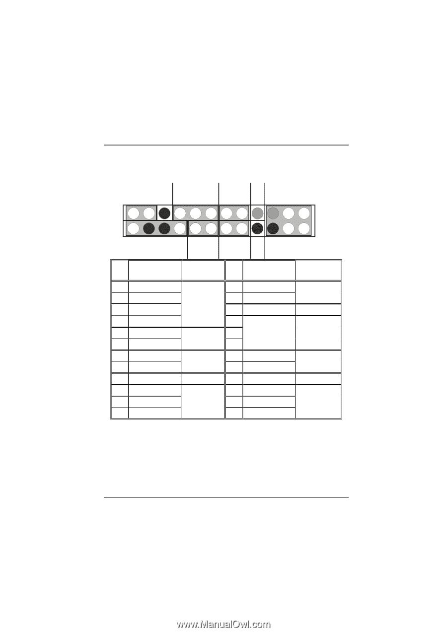
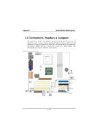
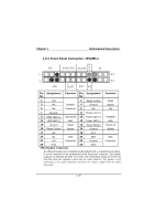
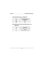
Chapter 1 Motherboard Description 1.6.1 Front Panel Connector: JPANEL1 K SLP POW-LED ON/OFF E IR (+) (+) (-) Y 2 24 1 23 SPK (+) (-) HLED RST NA Pin Assignment Function Pin Assignment Function No. No. 1 +5V 3 NA Speaker 2 Sleep Control 4 Ground Sleep Button 5 NA Connector 6 NA NA 7 Speaker 8 Power LED (+) 9 HDD LED (+) 11 HDD LED (-) Hard Drive 10 Power LED (+) LED 12 Power LED (-) POWER LED 13 Ground 15 Reset Control Reset Button 14 Power Button 16 Ground Power-on Button 17 NA 18 KEY 19 NA IrDA 20 KEY IrDA 21 +5V Connector 22 Ground Connector 23 IRTX 24 IRRX SPK (Speaker Connector) An offboard speaker can be installed on the motherboard as a manufacturing option. It can be connected to the motherboard at the front panel connector. The speaker (onboard or offboard) provides error beep code information during the Power On Self-Test when the computer cannot use the video interface. The speaker is not connected to the audio subsystem and does not receive output from the audio subsystem. 1-20
-
 1
1 -
2
-
3
-
4
-
5
-
6
-
7
-
8
-
9
-
10
-
11
-
12
-
13
-
14
-
15
-
16
-
17
-
18
-
19
-
 20
20 -
 21
21 -
 22
22 -
 23
23 -
 24
24 -
 25
25 -
 26
26 -
 27
27 -
 28
28 -
 29
29 -
 30
30 -
31
-
32
-
33
-
34
-
35
-
36
-
37
-
38
-
39
-
40
-
41
-
42
-
43
-
44
-
45
-
46
-
47
-
48
-
49
-
50
-
51
-
52
-
53
-
54
-
55
-
56
-
57
-
58
-
59
-
60
-
61
-
62
-
63
-
64
-
65
-
66
-
67
-
68
-
69
-
70
-
71
-
72
-
73
-
74
-
75
-
76
-
77
-
78
-
79
 |
 |