Biostar M7VIZ M7VIZ user's manual
Biostar M7VIZ Manual
 |
View all Biostar M7VIZ manuals
Add to My Manuals
Save this manual to your list of manuals |
Biostar M7VIZ manual content summary:
- Biostar M7VIZ | M7VIZ user's manual - Page 1
energy and, if not installed and used in accordance with the instructions, may cause harmful interference to radio communications. There is no guarantee vendor's approval in writing. The content of this user's manual is subject to be changed without notice and we will not be responsible for any mistakes - Biostar M7VIZ | M7VIZ user's manual - Page 2
Package contents ...4 How to set up Jumper 5 CPU Installation ...5 DDR DIMM Modules: DDR1, DDR2 6 Installing DDR Module 6 Jumpers, Headers, Connectors & Slots 7 DEUTSCH 14 Spezifikationen von M7VIZ 14 Verpackungsinhalt 15 Einstellung der Jumper 16 Installation der CPU 16 DDR DIMM Modules - Biostar M7VIZ | M7VIZ user's manual - Page 3
CCoonntteenntt TROUBLE SHOOTING 50 PROBLEMLÖSUNG 51 iii - Biostar M7VIZ | M7VIZ user's manual - Page 4
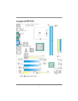
Layout of M7VIZ NOTE: ●represents the first pin. 1 - Biostar M7VIZ | M7VIZ user's manual - Page 5
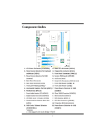
CD-ROM Audio-In Header (JCDIN1) Y. DDR Modules (DDR1-2) L. Communication Network Riser Slot Z. CPU Fan Connector (JCFAN1) (CNR1) A1 Frequency Selection (JCLK1) M. CNR Codec/ Onboard Selection B1 Power Source Selection for USB (JCODECSEL1) (JUSBV1) * optional ◎ only support with South Bridge - Biostar M7VIZ | M7VIZ user's manual - Page 6
English M7VIZ Features A. Hardware CPU Provides Socket A. Supports single AMD® Athlon/ Duron Family processor. Front Side Bus at 200/266/333 MHz. Chipset North Bridge: VIA KM400. South Bridge: VIA VT8235CE/ VT8237.(optional) Main Memory Supports up to 2 DDR devices. Supports 200/266/333 MHz (without - Biostar M7VIZ | M7VIZ user's manual - Page 7
ACPI. Supports USB Function. Software Supports Warpspeeder™, 9th Touch™, FLASHER™ and StudioFun! ™ (optional). Offers the highest performance for Windows 98 SE, Windows 2000, Windows Me, Windows XP, SCO UNIX etc. Package contents HDD Cable X 1 FDD Cable X 1 User's Manual X 1 Fully Setup Driver CD - Biostar M7VIZ | M7VIZ user's manual - Page 8
to how set up jumper. When the Jumper cap is placed on pins, the jumper is "close". If no jumper cap is placed on the pins, the jumper is "open". The illustration shows a 3-pin jumper whose pin1and 2 are "close" when jumper cap is placed on these 2 pins. Jumper open Jumper close Pin1-2 close CPU - Biostar M7VIZ | M7VIZ user's manual - Page 9
CPU Fan Header: JCFAN1 1 Pin 1 2 JCFAN1 3 Assignment Ground +12V FAN RPM rate Sense System Fan Header: JSFAN1 1 Pin 1 JSFAN1 2 3 Assignment Ground +12V FAN RPM rate Sense DDR DIMM Modules: DDR1, DDR2 DRAM Access Time: 2.5V Unbuffered/ Registered DDR 200 - Biostar M7VIZ | M7VIZ user's manual - Page 10
will attach directly to that video card. This motherboard supports video cards for PCI slots, supports modem only. Serial ATA Connector: JSATA1/ JSATA2 (only support with South Bridge VT8237) The motherboard has a PCI to SATA Controller with 2 channels SATA interface, it satisfies the SATA 1.0 spec - Biostar M7VIZ | M7VIZ user's manual - Page 11
NA 19 NA 21 +5V 23 IRTX Function Speaker Connector Hard Drive LED Reset Button IrDA Connector Pin Assignment 2 Sleep Control 4 Ground 6 NA 8 Power LED (+) 10 Power LED (+) 12 Power LED (-) 14 Power Button 16 Ground 18 KEY 20 KEY 22 Ground 24 IRRX Function Sleep Button NA - Biostar M7VIZ | M7VIZ user's manual - Page 12
standby voltage +5V Standby 1 Voltage Pin 2-3 close Note: In order to support the function "power-on the system via keyboard and mouse function, "JKBV1" jumper cap should be placed on pin 2-3. Power Source Selection for USB: JUSBV1/ JUSBV2/ JUSBV3 JUSBV1/JUSBV2/ Assignment JUSBV3 Description - Biostar M7VIZ | M7VIZ user's manual - Page 13
Wait for five seconds. 4. Set the jumper to "Pin 1-2 Close". 5. Power on the AC. 6. Reset your desired password or clear the CMOS data. Case Open Connector: JCI1 1 Pin Assignment 1 Case Open Signal JCI1 2 Ground Serial ATA Connector: JSATA1/ JSATA2 (only support with South Bridge VT8237 - Biostar M7VIZ | M7VIZ user's manual - Page 14
Pin Assignment 1 Mic In/ Center 2 Ground 3 Mic Power/ Bass 4 Audio Power 5 Right Line Out/ Speaker Out 6 Right Line Out/ 3 Assignment +5V_SB Ground Wake up Front USB Header: JUSB2, (JUSB1=>only support with South Bridge VT8237) Pin Assignment Pin Assignment 9 11 +5V(fused) - Biostar M7VIZ | M7VIZ user's manual - Page 15
Codec is used Frequency Selection: JCLK1 Pin 100 MHz 133 MHz 1-2 Open Open 3-4 Close Open 5-6 Open Open 7-8 Open Open 166 MHz Open Open Close Open Audio DJ: JDJ1 1 5 Pin Assignment Pin Assignment 1 SMBDT 2 SMBCK JDJ1 3 -INTR_B 4 NA 5 PWRGD 12 - Biostar M7VIZ | M7VIZ user's manual - Page 16
Back Panel Connectors JKBMS1 1394 PS/2 (optional) Mouse JPRNT1 Parallel Port JUSBLAN1 LAN Line In Speaker Out Mic In PS/2 USB COM1 Keyboard JCOM1 J1394_USB1 VGA1 JVGA1 USB JAUDIO 6 Channel Speakers Speaker Out Line In/ Rear Speaker Mic In/ Center & Bass 13 - Biostar M7VIZ | M7VIZ user's manual - Page 17
Deutsch Spezifikationen von M7VIZ A. Hardware CPU Unterstützung für Sockel A. Unterstützung für die AMD® Athlon/ Duron-Familie Prozessor. FSB mit 200/266/333 MHz. Chipsatz Northbridge: VIA KM400. Southbridge: VIA VT8235CE/ VT8237.(optional) Hauptspeicher Unterstützung für 2 DDR Geräte. Unterstützung - Biostar M7VIZ | M7VIZ user's manual - Page 18
2 USB2.0-Ports. (4 USB2.0-Ports sind für Southbridge VT8237) 1 Front-Audio-Header. 1 S/PDIF-Header. 1 1394A Firewire ports. (optional) Abmessungen ATX Form-Factor: 22.1 X 24.5cm (W X L) B. BIOS & Software BIOS Award legal Bios. Unterstützung für APM1.2. Unterstützung für ACPI. Unterstützung für USB - Biostar M7VIZ | M7VIZ user's manual - Page 19
diesen beiden Pins. Jumper geöffnet Jumper geschlossen Pin1-2 geschlossen Installation der CPU Schritt 1: Ziehen Sie den Hebel seitlich vom Sockel weg. Heben Sie den Hebel dann in 90-Grad-Winkel nach oben. Schritt 2: Suchen Sie nach der scharfen Kante, die auf Drehpunkt des Hebels weisen muss - Biostar M7VIZ | M7VIZ user's manual - Page 20
CPU-Lüfter Headers: JCFAN1 1 Pin 1 Beschreibung Masse JCFAN1 2 +12V 3 FAN RPM Geschwindigkeit Sensor System-Lüfter Headers: JSFAN1 1 Pin 1 JSFAN1 2 Beschreibung Masse +12V 3 FAN RPM Geschwindigkeit Sensor DDR DIMM Modules: DDR1, DDR2 DRAM-Zugriffszeit: 2.5V unbuffered DDR/Registered - Biostar M7VIZ | M7VIZ user's manual - Page 21
, und sie definieren eine Hardware-skalierbare Riser-Card-Schnittstelle, welche nur Audio, Netzwerk und Modem unterstützt. Serial ATA Connector: JSATA1/ JSATA2 (nur für Southbridge VT8237) Auf diesen Motherboard gibt es ein PCI-to-SATA Controller mit 2-Kanal Interface, die der Spezifikation von - Biostar M7VIZ | M7VIZ user's manual - Page 22
ckstell- 15 Reset-Kontroll knopf 17 Kein 19 Kein IrDA- 21 +5V Anschluss 23 IRTX Pin Belegung 2 Schlaf- Kontroll 4 Masse 6 Kein 8 Power LED (+) 10 Power LED (+) 12 Power LED (-) 14 Power-Knopf 16 Masse 18 Schlüsse 20 Schlüsse 22 Masse 24 IRRX Funktion SchlafKnopf Kein - Biostar M7VIZ | M7VIZ user's manual - Page 23
1 +5V Pin 1-2 geschlossen 3 Durch +5V reservierte Spannung für PS/2-Maus und PS/2-Tastatur zum 1 +5V reservierte Spannung Erwecken vom System Pin 2-3 geschlossen Anmerkung: Um die Funktion ─"Erwecken durch Tastatur/Maus" ─ zu aktivieren, müssen Pins 2-3 von JKBV1 durch die Jumperkappe - Biostar M7VIZ | M7VIZ user's manual - Page 24
Jumper zum Löschen des CMOS: JCMOS1 JCMOS1 Beschreibung 3 1 Pin 1-2 geschlossen Normale Operation (Default) 3 1 Pin 2-3 geschlossen CMOS-Daten Löschen ※ Prozeduren zum Löschen des CMOS: 1. Ausschalten Sie das System. 2. Lassen Sie Pin 2-3 von JCOMS1 geshclossen sein. 3. Bitte warten Sie 15 - Biostar M7VIZ | M7VIZ user's manual - Page 25
Wake On LAN Header: JWOL1 Belegung Masse Audio-Betriebsspannung Audio-Signal des rechten Kanals zur Vorderseite Kein Pin Audio-Signal des linken Kanals zur Vorderseite Audio-Signal des rechten Kanals von der Vorderseite Audio-Signal des linken Kanals von der Vorderseite Pin 1 1 2 JWOL1 - Biostar M7VIZ | M7VIZ user's manual - Page 26
Verwendung von CNR-Codec Pin 100 MHz 133 MHz 166 MHz 1-2 öffnen öffnen öffnen 3-4 schließen öffnen 5-6 öffnen öffnen öffnen schließen 7-8 öffnen Audio DJ: JDJ1 öffnen öffnen 1 5 Pin Belegung Pin Belegung 1 SMBDT 2 SMBCK JDJ1 3 -INTR_B 4 Kein Pin 5 PWRGD 23 - Biostar M7VIZ | M7VIZ user's manual - Page 27
Anschlüsse für die Rückwand JKBMS1 1394 PS/2- (optional) Maus JPRNT1 Parallel PS/2- USB COM1 Tastatur J1394_USB1 JCOM1 VGA1 JVGA1 JUSBLAN2 LAN Line-In Lautsprecher- Ausgang MikrofonAusgang USB JAUDIO 6-Kanal-Lautsprecher LaursprecherAusgang Line-In/ LautsprecherEingang Mikrofon-Eingang / - Biostar M7VIZ | M7VIZ user's manual - Page 28
Français Caractéristiques de la M7VIZ A. Matériel Processeur Fournit un support Socket A. Prend en charge un unique processeur AMD® de la famille Athlon/ Duron. Bus face avant à 200/266/333 MHz. Chipset Pont nord : VIA KM400. Pont sud : VIA VT8235CE/ VT8237.(option) Mémoire principale Prend en - Biostar M7VIZ | M7VIZ user's manual - Page 29
2 ports USB2.0. (4 ports USB2.0 uniquement avec le pont sud VT8237) 1 connecteur audio avant. 1 connecteur S/PDIF. 1 port 1394A Firewire. (option) Dimensions Facteur de forme ATX: 22,1 X 24,5cm (l X L) B. BIOS et logiciel BIOS BIOS Award. Prend en charge APM1.2. Prend en charge ACPI. Prend en charge - Biostar M7VIZ | M7VIZ user's manual - Page 30
It plays DVD, VCD, MP3, Audio CD and various other known file formats. You can take snapshots of video and customize the saved images as screensavers. You can also store the images on USB mass storage devices like flash disks and USB floppy disks. Hardware Requirements The supported hardware list of - Biostar M7VIZ | M7VIZ user's manual - Page 31
terminate the installation and reboot the machine. If Windows or GNU/Linux is the only OS installed use the free space. After installing the base system you will be prompted to select the resolution the type of mouse installed. The distribution currently supports PS/2, USB and Serial mice. In case of - Biostar M7VIZ | M7VIZ user's manual - Page 32
of a MBR corruption, this option should be used. It will automatically probe the hard disk master boot record and find out the installed operating system(s). On success it will re-install the boot loader with correct options in the MBR. Any custom boot loader option specified from other GNU/Linux - Biostar M7VIZ | M7VIZ user's manual - Page 33
After complete boot up, you get to the main Desktop screen. The following section is a complete description of the Desktop application. Desktop This is the main shell of the StudioFun software. It basically comprises of two categories, one is the main "media control" part and the other is the " - Biostar M7VIZ | M7VIZ user's manual - Page 34
running, otherwise, the control will simply glow to inform the user about a AUDIO present in the DVD/CD-ROM drive. 5. FILE This control will glow whenever a File CD (CDs with other media type files) is detected in a DVD/CD-ROM drive. The File CD will be auto-played only when it is put in to - Biostar M7VIZ | M7VIZ user's manual - Page 35
this icon will invoke the application for changing the screen resolutions. Refer to section 5.4, Display Settings for more details. 4. File Manager Clicking this icon will invoke the file manager. Refer to section 5.6 File manager for more details. When user has a DVD and a CD-ROM Drive: If user has - Biostar M7VIZ | M7VIZ user's manual - Page 36
, hue, saturation adjusting requires hardware/driver support) i. Playlists j. Image snapshot k. Audio resampling l. Software de-interlacing algorithms m. Configuration dialog n. Aspect ratio changing o. Fullscreen display • Supported File formats a. Video CD b. MPEG program streams (.mpg, .mpeg - Biostar M7VIZ | M7VIZ user's manual - Page 37
g. MPEG-Audio (.mp2, .mp3) h. WAV (.wav) Video Codecs i. MPEG 1/2 j. MPEG 4 (aka OpenDivX) k. MS MPEG 4 a. Chapter 5: Software Details 10 l. Windows Media Video 7 m. Motion JPEG • Remote Control support. a. Infrared interface b. User-friendly • Usage of StudioFun! with CelomaChrome skin a. Select - Biostar M7VIZ | M7VIZ user's manual - Page 38
o. Select setup button to modify the settings of the player p. Select f.scr button to show the video output of the player in full screen file to play Error Messages The following error message is given if an unknown file format is selected through Xine MRL browser and played. While playing mp3 files - Biostar M7VIZ | M7VIZ user's manual - Page 39
: The screensaver will blank the screen after the keyboard and mouse have been idle default time is 1minute and user can change the settings. • Cycle After Option: When screensaver is running this cycle time defines the time limit for each screensaver. • Mode Screensaver comes with various modes - Biostar M7VIZ | M7VIZ user's manual - Page 40
images is 5 seconds. Hyperball Hypercube Halo Strange • A snapshot of the application is shown below: Display Settings Display Settings Display setting is a program to change the current resolution settings of the Display. By default user of StudioFun will be given a choice to select between any of - Biostar M7VIZ | M7VIZ user's manual - Page 41
any device. Select device - Contains the device names /floppy, /cdrom and /flashdisk. Select a device from/to which you want to copy files. Please double click the device option twice to mount the device. List Directories - Shows the list of directories of the selected device after double clicking - Biostar M7VIZ | M7VIZ user's manual - Page 42
39 - Biostar M7VIZ | M7VIZ user's manual - Page 43
setting is not appropriate when testing and results in system fail or hang, [ WarpSpeeder™ ] technology assures the system stability by automatically rebooting the computer and then restart to a speed that is either the original system speed or a suitable one. System Requirement OS Support: Windows - Biostar M7VIZ | M7VIZ user's manual - Page 44
Installation 1. Execute the setup execution file, and then the following dialog will pop up. Please click "Next" button and follow the default procedure to install. 2. When you see the following dialog - Biostar M7VIZ | M7VIZ user's manual - Page 45
Usage The following figures are just only for reference, the screen printed in this user manual will change according to your motherboard on hand. [WarpSpeeder™] includes 1 tray icon and 5 panels: 1. Tray Icon: Whenever the Tray Icon utility is launched, it will display a little tray icon on the - Biostar M7VIZ | M7VIZ user's manual - Page 46
[ WarpSpeeder™ ] utility will be invoked. Please refer do the following figure; the utility's first window you will see is Main Panel. Main Panel contains features as follows: a. Display the CPU Speed, CPU external clock, Memory clock, AGP clock, and PCI clock information. b. Contains About, Voltage - Biostar M7VIZ | M7VIZ user's manual - Page 47
and the Voltage Panel will slide out to up as the following figure. In this panel, you can decide to increase CPU core voltage and Memory voltage or not. The default setting is "No". If you want to get the best performance of overclocking, we recommend you click the option "Yes". 44 - Biostar M7VIZ | M7VIZ user's manual - Page 48
4. Overclock Panel Click the Overclock button in Main Panel, the button will be highlighted and the Overclock Panel will slide out to left as the following figure. 45 - Biostar M7VIZ | M7VIZ user's manual - Page 49
3MHz button": provide user the ability to do real-time overclock adjustment. Warning: Manually overclock is potentially dangerous, especially when the overclocking percentage is over 110 %. We ": Pop up the following dialog. Let user select a restoring way if system need to do a fail-safe reboot. 46 - Biostar M7VIZ | M7VIZ user's manual - Page 50
d. "Auto-overclock button": User can click this button and [ WarpSpeeder™ ] will set the best and stable performance and frequency automatically. [ WarpSpeeder™ ] utility will execute a series of testing until system fail. Then system will do fail-safe reboot by using Watchdog function. After reboot - Biostar M7VIZ | M7VIZ user's manual - Page 51
as the following figure. In this panel, you can get the real-time status information of your system. The information will be refreshed every 1 second. 6. About Panel Click the About button in . You can also get the mainboard's BIOS model and the Version number of [ WarpSpeeder™ ] utility. 48 - Biostar M7VIZ | M7VIZ user's manual - Page 52
hardware monitor features are controlled by several separate chipset, [ WarpSpeeder™ ] divide these features to separate panels. If one chipset is not on board, the correlative button in Main panel will be disabled, but will not interfere other panels' functions. This property can make [ WarpSpeeder - Biostar M7VIZ | M7VIZ user's manual - Page 53
SOLUTION Screen message says "Invalid Configuration" or * Review system's equipment . Make sure "CMOS Failure." correct information is in setup. PROBABLE SOLUTION Cannot boot system after installing second hard * Set master/slave jumpers correctly. drive. * Run SETUP program and select - Biostar M7VIZ | M7VIZ user's manual - Page 54
" oder "CMOS Fehler." versichern Sie sich, das diese richtig eingerichtet sind. MÖGLICHE URSACHE LÖSUNG Das System kann nach der Installation einer * Setzen Sie die Master/Slave-Jumper richtig ein. zweiten Festplatte nicht hochgefahren werden. * Führen Sie das SETUP-Programm aus und wählen Sie - Biostar M7VIZ | M7VIZ user's manual - Page 55
06/20/2003 52
-
 1
1 -
 2
2 -
 3
3 -
 4
4 -
 5
5 -
 6
6 -
 7
7 -
8
-
9
-
10
-
11
-
12
-
13
-
14
-
15
-
16
-
17
-
18
-
19
-
20
-
21
-
22
-
23
-
24
-
25
-
26
-
27
-
28
-
29
-
30
-
31
-
32
-
33
-
34
-
35
-
36
-
37
-
38
-
39
-
40
-
41
-
42
-
43
-
44
-
45
-
46
-
47
-
48
-
49
-
50
-
51
-
52
-
53
-
54
-
55
 |
 |

M
M
7
7
V
V
I
I
Z
Z
i
FCC Information and Copyright
This equipment has been tested and found to comply with the limits of a
Class B digital device, pursuant to Part 15 of the FCC Rules. These limits
are designed to provide reasonable protection against harmful
interference in a residential installation. This equipment generates, uses
and can radiate radio frequency energy and, if not installed and used in
accordance with the instructions, may cause harmful interference to radio
communications. There is no guarantee that interference will not occur in
a particular installation.
The vendor makes no representations or warranties with respect to the
contents here of and specially disclaims any implied
warranties
of
merchantability or fitness for any purpose. Further the vendor reserves
the right to revise this publication and to make changes to the contents
here of without obligation to notify any party beforehand.
Duplication of this publication, in part or in whole, is not allowed without
first obtaining the vendor’s approval in writing.
The content of this user’s manual is subject to be changed without notice
and we will not be responsible for any mistakes found in this user’s
manual. All the brand and product names are trademarks of their
respective companies.