Biostar MCP6P-M2 Setup Manual
Biostar MCP6P-M2 Manual
 |
View all Biostar MCP6P-M2 manuals
Add to My Manuals
Save this manual to your list of manuals |
Biostar MCP6P-M2 manual content summary:
- Biostar MCP6P-M2 | Setup Manual - Page 1
MCP6P-M2 Setup Manual FCC Information and Copyright This equipment has been tes ted and c an radiate radio frequency energy and, if not ins talled and used in accordance with the instructions , may cause harmful interference to radio communications . There is no guarantee that interference will not - Biostar MCP6P-M2 | Setup Manual - Page 2
3.2 Detail Settings ...14 Chapter 4: RAID Functions ...21 4.1 Operation System...21 4.2 Raid Arrays...21 4.3 How RAID Works...21 Chapter 5: Useful Help ...25 5.1 Driver Installation Note ...25 5.2 Award BIOS Beep Code ...26 5.3 Extra Information...26 5.4 Troubleshooting...27 A ppendencies: SPEC In - Biostar MCP6P-M2 | Setup Manual - Page 3
X 1 Installation Guide X 1 Fully Se tup Drive r C D X 1 (full ve rsion manual files inside ) FDD Cable X 1 (optional) Se rial ATA Powe r Cable X 1 (optional) USB 2.0 Cable X1 (optional) S/PDIF out Cable X 1 (optional) Note: The package contents may differ by area or your motherboard version. 3 - Biostar MCP6P-M2 | Setup Manual - Page 4
Motherboard Manual 1.3 MOT HERBOARD FEAT URES SPEC Socket AM2 AMD 64 Architectu re enables 32 and 64 bit compu ting Supports Hyper Tran sport and Cool= n =Quiet CPU AMD Ath lon 64 / Ath lon 64 FX / Athlon 64 x2 / Sempron processors FSB Chipset Supports up to 1 GHz Bandwidth Support HyperTran - Biostar MCP6P-M2 | Setup Manual - Page 5
MCP6P-M2 SPEC S/PDIF ou t conn ector CPU Fan header System Fan header CMOS clear header USB conn ector Power Conn ector (24pin) Power Conn ector (4pin) PS/2 Keyboard PS/2 Mouse Back Panel I/O VGA port Serial Port LAN port USB Port Audio Jack Board Size 190 mm(W) x 244 mm(L) Special Features RAID 0 / - Biostar MCP6P-M2 | Setup Manual - Page 6
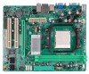
Motherboard Manual 1.5 JKBMS1 MOT HERBOARD LAYOUT JCFA N1 JATXP WR4 JKBM SPWR1 DIMMA1 J US BPWR1 JUSB1 JATXP WR1 JUSBLAN1 JUSBPW R2 IDE1 BIOS JA UDIO1 nForce 6100-430 JCDIN1 JA UDIOF 1 DIMMB1 J US B3 JUSB2 J US B4 J CMOS1 SATA 3 Super I/O JCOM1 Socket VGA A M2 L AN PCI-EX16 BAT1 PCI1 - Biostar MCP6P-M2 | Setup Manual - Page 7
MCP6P-M2 CHAPTER 2: HARDWARE INSTALLATION 2.1 INST ALLING CENT RAL PROCESSING UNIT (CPU) Step 1: Remove the socket protection cap. Step 2: Pull the lever toward direction A from the socket and then raise the lever up to a 90-degree angle. Step 3: Look for the white triangle on socket, and the - Biostar MCP6P-M2 | Setup Manual - Page 8
Motherboard Manual Step 4: Hold the CPU down firmly, and then close the lever toward direct B to complete the installation. Step 5: Put the CPU Fan on the CPU and buckle it. Connect the CPU FAN power cable to the JCFAN1. This completes the installation. 8 - Biostar MCP6P-M2 | Setup Manual - Page 9
MCP6P-M2 2.2 FAN HEADERS These fan headers support cooling-fans built in the computer. The fan cable and connector may be different according to the fan manufacturer. Connect the fan cable to the connector while matching the black wire to pin#1. JCFAN1: CPU Fan Heade r 1 4 Pin 1 2 3 4 - Biostar MCP6P-M2 | Setup Manual - Page 10
Motherboard Manual 2.3 INST ALLING SYST EM MEMORY A. Memory Modules 1. Unlock a DIMM slot by pressing the retaining clips outward. Align a DIMM on the slot such that the notch on the DIMM matches the break on the Slot. 2. Insert the DIMM vertically and firmly into the slot until the retaining - Biostar MCP6P-M2 | Setup Manual - Page 11
MCP6P-M2 B. Memory Capacity DIMM Socket Location DIMMA1 DIMMB1 DDR2 Module 256MB/512MB/1GB/2GB 256MB/512MB/1GB/2GB Total Memory Size Max is 4GB. C. Dual Channel Memory installation To trigger the Dual Channel f unction of the motherboard, the memory module must meet the following requirements: - Biostar MCP6P-M2 | Setup Manual - Page 12
Motherboard Manual 2.4 CONNECT ORS AND SLOT S The motherboard prov ides a standard floppy disk connector that supports 360K, 720K, 1.2M, 1.44M and 2.88M floppy disk ty pes. This connector supports the prov ided f loppy drive ribbon cables. FDD1: Floppy Disk Conne ctor 2 1 34 33 IDE1: Hard Disk - Biostar MCP6P-M2 | Setup Manual - Page 13
MCP6P-M2 PCI-EX16: PCI-Express x16 Slot PCI-Express 1.0a compliant. Maximum theoretical realized bandwidth of 4GB/s simultaneously per direction, f or an aggregate of 8GB/s totally. PCI-Express supports a raw bit-rate of 2.5GB/s on the data pins. 2X bandwidth ov er the traditional PCI architecture. - Biostar MCP6P-M2 | Setup Manual - Page 14
Motherboard Manual CHAPTER 3: HEADERS & JUMPERS SETUP 3.1 HOW T O SET UP JUMPERS The illustration shows how to set up jumpers. When the jumper cap is placed on pins, the jumper is "close", if not, that means the jumper is "open". Pin opened Pin - Biostar MCP6P-M2 | Setup Manual - Page 15
MCP6P-M2 JATXPWR1: ATX Powe r Source Conne ctor This connector allows user to connect 24-pin power connector on the +12V +3.3V JATXPWR4: ATX Powe r Source Conne ctor By connecting this connector, it will provide +12V to CPU power circuit. 1 2 4 3 Pin 1 2 3 4 Assignment +12V +12V Ground Ground 15 - Biostar MCP6P-M2 | Setup Manual - Page 16
Motherboard Manual JUSB2/JUSB3/JUSB4: He ade rs for USB 2.0 Ports at Front Panel This header allows user to connect additional USB cable on the PC f ront panel, and also can be connected with internal USB devices, like USB card reader. Pin Assignment +5V (fused) +5V (fused) USBUSBUSB+ USB+ Ground - Biostar MCP6P-M2 | Setup Manual - Page 17
MCP6P-M2 JAUDIO F1: Front Panel Audio Heade r This header allows user to connect the front audio output cable with the PC f ront panel. This header allows only HD audio front panel connector; AC'97 connector is not acceptable. 10 2 9 1 Pin 1 2 3 4 5 6 7 8 9 10 Assignment Mic Left in Ground Mic - Biostar MCP6P-M2 | Setup Manual - Page 18
Motherboard Manual JSPDIF_O UT1: Digital Audio-out Conne ctor This connector allows user to connect the PCI bracket SPDIF output header. Pin 1 2 3 Assignment +5V SPDIF_OUT Ground 1 3 JCMO S1: Cle ar CMOS Heade r By placing the jumper on pin2-3, it allows user to restore the BIOS saf e setting - Biostar MCP6P-M2 | Setup Manual - Page 19
MCP6P-M2 JPRNT1: Printe r Port Connector This header allows you to connector printer on the PC. 2 1 25 Pin 1 2 3 4 5 6 7 8 9 10 11 12 13 Assignment -Strobe -ALF Data 0 -Error - Biostar MCP6P-M2 | Setup Manual - Page 20
Motherboard Manual JUSBPWR1/JUSBPWR2: Powe r Source Heade rs for USB Ports Pin 1-2 Close: JUSBPWR1: +5V for USB ports at JUSB1/JUSBLAN1. JUSBPWR2: +5V for USB ports at f ront panel (JUSB2/JUSB3/JUSB4). Pin 2-3 Close: JUSBPWR1: USB voltage. Note: In order to support this func tion "Power-on s ystem - Biostar MCP6P-M2 | Setup Manual - Page 21
MCP6P-M2 CHAPTER 4: RAID FUNCTIONS 4.1 O PERAT ION SYST EM z Supports Windows XP Home/Prof essional Edition, and Windows 2000 Prof essional. 4.2 RAID ARRAYS RAID supports by the stripe size parameter, which you set during the creation of the RAID set based on the system environment. This - Biostar MCP6P-M2 | Setup Manual - Page 22
Motherboard Manual RAID 1: Every read and write is actually carried out in parallel be applied for high-availability solutions, or as a form of automatic backup that eliminates tedious manual backups to more expensive and less reliable media. Features and Benefits Drives: Minimum 2, and maximum - Biostar MCP6P-M2 | Setup Manual - Page 23
MCP6P-M2 RAID 0+1: RAID 0 drives can be mirrored using RAID 1 techniques. Resulting in a RAID 0+1 solution for improved performance plus resiliency. Features and Benefits Drives: Minimum 4, and maximum - Biostar MCP6P-M2 | Setup Manual - Page 24
Motherboard Manual processing and general purpose service. Benefits: An ideal combination as a single disk. Write perf ormance can be CPU intensiv e. Fault Tolerance: Yes. Dis k 1 DATA Driver CD, or go to http://www.nvidia.com/object/IO_28159.html to download the NVIDIA RAID User's Guide. 24 - Biostar MCP6P-M2 | Setup Manual - Page 25
MCP6P-M2 CHAPTER 5: USEFUL HELP 5.1 DRIVER INST ALLAT ION NOT E After you installed your operating system, please insert the Fully Setup Driver CD into your optical drive and install the driver for better system performance. You will see the following window after you insert the CD The setup guide - Biostar MCP6P-M2 | Setup Manual - Page 26
Motherboard Manual 5.2 AWARD BIOS BEEP CODE Meaning Video card not found or v ideo card memory bad CPU overheated System will shut down automatically Beep Sound One long beep followed by two short beeps High-low siren sound One Short beep when system boot-up No error found during POST Long beeps - Biostar MCP6P-M2 | Setup Manual - Page 27
MCP6P-M2 5.4 1. TROUBLESHOOT ING Probable Solution 1. Make sure power cable is No power to the system at all securely plugged in. Power light don't illuminate, f an inside power supply does not turn 2. Replace cable. on. 3. Contact technical support. 2. Indicator light on key board does not turn - Biostar MCP6P-M2 | Setup Manual - Page 28
Motherboard Manual APPENDENCIES: SPEC IN OTHER LANGUAGE GERMAN Spezifikationen Sockel AM2 CPU Die AMD 64-Architektur un terstü tzt eine 32-Bit- und AMD Arbeitsspeich Max. 4GB Arbeitsspeicher er Jeder DIMM unterstü tzt 256MB/512 MB/1G ATA-Controller LAN Realtek RTL 8201CL Audio-Codec ALC662 - Biostar MCP6P-M2 | Setup Manual - Page 29
tzt die CD Audio-In-Funktion Unterstü tzt die digitale Audioausgabefunktion CPU-Lüfterstromversorgungsansch luss (mit Smart Fan-Fun ktion) System-Lüfter-Stromversorgungsan schlu ss Unterstü tzt RAID 0 / 1 / 0+1 / 5 Biostar behält sich das Recht vor , ohn e An kündigung Windows 2000 / XP / VISTA die - Biostar MCP6P-M2 | Setup Manual - Page 30
Motherboard Manual FRANCE SPEC Socket AM2 UC Processeu rs AMD Ath lon 64 / Athlon 64 FX / Ath lon 64 x2 / Sempron Bus f rontal Chipset Prend en charge Hyper Tran sport ju squ' - Biostar MCP6P-M2 | Setup Manual - Page 31
Port LAN Port USB Fiche audio Dimen sions de la carte Fonctionnali tés spéciales Support SE Windows 2000 / XP / VISTA Prise en charge RAID 0 / 1 / 0 +1 / 5 190 mm (l) X 244 mm (H) x1 x1 x1 x1 x1 x4 x3 x1 x1 x1 x1 x1 x1 x3 x1 Chaque connecteur prend en ch arge 2 ports USB de panneau avan t Biostar - Biostar MCP6P-M2 | Setup Manual - Page 32
Motherboard Manual IT ALIAN SPECIFICA Socket AM2 CPU L'architettura AMD 64 abilita l a computazione 32 Processori AMD Athlon 64 / Athlo n 64 e 64 bit FX / Athlon 64 x 2 / Sempro n Supporto di Hyper Tra nsport e Cool' n'Quiet FSB Chipset Supporto di Hyper Transport fi no - Biostar MCP6P-M2 | Setup Manual - Page 33
) Alimentazione ve ntolina di sistema posteriore Porta LAN Porta USB Connettore audio Dimension i scheda Caratterist iche speciali Sistemi operativi supportati Windows 2000 / XP / VISTA Supporto RAID 0 / 1 / 0+1 / 5 190 mm (larghezza) x 244 mm (altezza) Biostar si riserva il diritto di aggiungere - Biostar MCP6P-M2 | Setup Manual - Page 34
Motherboard Manual SPANISH Especificación Conector AM2 CPU La arqu itectu ra AMD 64 permite el procesado de 32 y Procesadores AMD Athlon 64 DDR2 de canal Doble Admite DDR2 de 533 / 667 / 800 No admite DIMM registrados o DIMM compatibles con ECC Memoria máxima de vídeo compartida de 512MB Modo bu s - Biostar MCP6P-M2 | Setup Manual - Page 35
Tamaño de la placa Funciones especiales Soporte de sistema operativo Windows 2000 / XP / VISTA 190 mm. (A) X 244 Mm. (H) X1 X1 X1 X1 X1 X4 X3 X1 X1 X3 X1 Cada conector soporta 2 puertos USB fron tales Admite RAID 0 / 1 / 0 +1 / 5 Biostar se reserva el derecho de añ adir o retirar el soporte de - Biostar MCP6P-M2 | Setup Manual - Page 36
Motherboard Manual PORT UGUESE ESPECIFICAÇÕES Socket AM2 CPU A arquitectu ra AMD 64 permite uma compu tação de 32 Processadores AMD Ath lon 64 / Ath lon 64 e 64 bits FX / Ath lon 64 x2 / Sempron Suporta as tecn ologias Hyper Tran sport e Cool'n 'Qu iet FSB - Biostar MCP6P-M2 | Setup Manual - Page 37
Entradas/S aídas no painel traseiro Rato PS/2 Porta VG A Porta série Porta LAN Porta USB Tomada de áudio Tamanho da placa Característi cas especiais Sistemas operativos suportados Windows 2000 / XP / VISTA A Biostar reserva-se o direito de adicionar ou remover suporte para qualquer sistema operativo - Biostar MCP6P-M2 | Setup Manual - Page 38
Motherboard Manual POLISH SPEC Socket AM2 Procesor Architektu ra AMD 64 umoż liwia przetwarzanie 32 i 64 AMD DIMM oraz ECC DIMM Funkcj e kon troli warun ków pracy , Pamięć główna Maks. wielkość pamięci 4G B Każ de gniazdo DIMM kanałowe wyjście audio Obs ługa High-Def inition Audio x2 x1 x1 x1 LAN - Biostar MCP6P-M2 | Setup Manual - Page 39
Złącze główkowe kasowania CMOS Złącze USB Złącze zasilania (24 pinowe) Złącze zasilania (4 pinowe) Klawiatu ra PS/2 Mysz PS/2 Back Panel I/O Port VG A Port szeregowy Port LAN Port USB Gniazdo audio Wymiary płyty Funkcj e specjaln e Obsluga systemu operacyjne go Windows 2000 / XP / VISTA 190 mm - Biostar MCP6P-M2 | Setup Manual - Page 40
Motherboard Manual RUSSIAN СПЕЦ CPU (центральн ый процессор) FSB Набор микросхем Гнездо AM2 Процессоры AMD Ath lon 64 / Athlon 64 FX / Ath lon 64 X2 / Sempron Поддержка HyperTran sport с пропускной способностью до1GГц nForce 6100-430 Слоты DDR2 DIMM x 2 Основная память Максимальная ёмкость памяти 4 - Biostar MCP6P-M2 | Setup Manual - Page 41
MCP6P-M2 СПЕЦ - Biostar MCP6P-M2 | Setup Manual - Page 42
Motherboard Manual ARABIC اﻟﻤﻮاﺻﻔﺎت ﺮﻋﺔ 32و 64ﺏﺖ AMD 64ﺗﻤﻜﻦ ﺗﻘﻨﻴﺔ ﻟﺤﺎﺳﻮﺏﻴﺔ ﺏﺴ - Biostar MCP6P-M2 | Setup Manual - Page 43
MCP6P-M2 اﻟﻤﻮاﺻﻔﺎت ﻳﺪﻋﻢ ﺗ - Biostar MCP6P-M2 | Setup Manual - Page 44
Motherboard Manual JAPANESE 仕様 Socket AM2 CPU AMD Ath lon 64 / Ath lon 64 FX / Athlon 64 x2/ Sempron プロセッサ 1GHzのバンド幅までハイパートランスポート をサポートします チップセット nForce 6100-430 DDR2 DIMMスロット x 2 最大メモリ容量4GB メインメモリ 各DIMMは 256 MB/512MB & 1GB/2G B DDR2をサポート ITE 8716F Super I/O デュアル チャンネルモードDDR2 メモリモジュール DDR2 533 / - Biostar MCP6P-M2 | Setup Manual - Page 45
MCP6P-M2 仕様 SATAコネクタ フロントパネルコネクタ フロントオーディオコネクタ CDインコネクタ S/PDIFアウトコネクタ CPUファンヘッダ システ
-
 1
1 -
 2
2 -
 3
3 -
 4
4 -
 5
5 -
 6
6 -
 7
7 -
8
-
9
-
10
-
11
-
12
-
13
-
14
-
15
-
16
-
17
-
18
-
19
-
20
-
21
-
22
-
23
-
24
-
25
-
26
-
27
-
28
-
29
-
30
-
31
-
32
-
33
-
34
-
35
-
36
-
37
-
38
-
39
-
40
-
41
-
42
-
43
-
44
-
45
 |
 |

MCP6P-M2 Setup Manual
FCC Information and Copyright
This equipment has been tested and found to comply with the limits of a Class
B digital device, pursuant to Part 15 of the FCC Rules. These limits are designed
to provide reasonable protection against harmful interference in a residential
installation. This equipment generates, uses, and can radiate radio frequency
energy and, if not installed and used in accordance with the instructions, may
cause harmful interference to radio communications. There is no guarantee
that interference will not occur in a particular installation.
The vendor makes no representations or warranties with respect to the
contents here and specially disclaims any implied warranties of merchantability
or fitness for any purpose. Further the vendor reserves the right to revise this
publication and to make changes to the contents here without obligation to
notify any party beforehand.
Duplication of this publication, in part or in whole, is not allowed without first
obtaining the vendor’s approval in writing.
The content of this user’s manual is subject to be changed without notice and
we will not be responsible for any mistakes found in this user’s manual. All the
brand and product names are trademarks of their respective companies.