Biostar MCP6P-M2 Setup Manual - Page 16
Biostar MCP6P-M2 Manual
 |
View all Biostar MCP6P-M2 manuals
Add to My Manuals
Save this manual to your list of manuals |
Page 16 highlights
Motherboard Manual JUSB2/JUSB3/JUSB4: He ade rs for USB 2.0 Ports at Front Panel This header allows user to connect additional USB cable on the PC f ront panel, and also can be connected with internal USB devices, like USB card reader. Pin Assignment +5V (fused) +5V (fused) USBUSBUSB+ USB+ Ground Ground Key NC JUSB3 JUSB2 JUSB4 2 1 10 9 1 2 3 4 5 6 7 8 9 10 SATA1~SATA4: Se rial ATA Connectors The motherboard has a PCI to SATA Controller with 4 channels SATA interf ace. SATA3 SATA4 SATA1 SATA2 1 4 7 Pin 1 2 3 4 5 6 7 Assignment Ground T X+ T XGround RXRX+ Ground 16
-
 1
1 -
2
-
3
-
4
-
5
-
6
-
7
-
8
-
9
-
10
-
 11
11 -
 12
12 -
 13
13 -
 14
14 -
 15
15 -
 16
16 -
 17
17 -
 18
18 -
 19
19 -
 20
20 -
 21
21 -
22
-
23
-
24
-
25
-
26
-
27
-
28
-
29
-
30
-
31
-
32
-
33
-
34
-
35
-
36
-
37
-
38
-
39
-
40
-
41
-
42
-
43
-
44
-
45
 |
 |

Motherboard Manual
16
JUSB2/JUSB3/JUSB4: Headers for USB 2.0 Ports at Front Panel
This header allows user to connect additional USB cable on the PC f ront panel,
and also can be connected with internal USB devices, like USB card reader.
Pin
Assignment
1
+5V (fused)
2
+5V (fused)
3
USB-
4
USB-
5
USB+
6
USB+
7
Ground
8
Ground
9
Key
10
NC
1
2
9
JUSB3
JUSB2
JUSB4
10
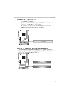
SATA1~SATA4: Serial ATA Connectors
The motherboard has a PCI to SATA Controller with 4 channels SATA interf ace.
Pin
Assignment
1
Ground
2
TX+
3
TX-
4
Ground
5
RX-
6
RX+
1
4
7
SATA3
SATA1 SATA2
SATA4
7
Ground