Biostar P4M900-M7 FE Setup Manual
Biostar P4M900-M7 FE Manual
 |
View all Biostar P4M900-M7 FE manuals
Add to My Manuals
Save this manual to your list of manuals |
Biostar P4M900-M7 FE manual content summary:
- Biostar P4M900-M7 FE | Setup Manual - Page 1
P4M900-M7 FE Setup Manual FCC Information and Copyright This equipment has been tes ted an radiate radio frequency energy and, if not ins talled and used in accordance with the instructions , may cause harmful interference to radio communications . There is no guarantee that interference will not - Biostar P4M900-M7 FE | Setup Manual - Page 2
System 20 4.2 Raid Arrays 20 4.3 How RAID Works 20 Chapter 5: Useful Help 22 5.1 Driver Installation Note 22 5.2 Award BIOS Bee p Code 23 5.3 Extra Information 23 5.4 Tro ubles ho oting 24 A ppendencies: SPEC In Other Language 26 Ge rman 26 France 28 Italian 30 Spanish 32 - Biostar P4M900-M7 FE | Setup Manual - Page 3
P4M900-M7 FE CHAPTER 1: INTRODUCTION 1.1 BEFORE YOU START Thank you for as hea t source , humid air and wate r. 1.2 PACKAGE CHECKLIST HDD Cable X 1 Installation Guide X 1 Fully Se tup Drive r C D X 1 (full ve rsion manual files inside ) Rear I/O Panel for ATX Case X 1 FDD Cable X 1 (optional) Se - Biostar P4M900-M7 FE | Setup Manual - Page 4
Motherboard Manual 1.3 MOT HERBOARD FEAT URES SPEC LGA 775 Intel Core2Duo/ Pe ntium 4 / Pentium Supports Hy per Thre ading/ Execute Disable Bit/ CPU D / Celero n D / C eleron 4xx processor Enha nced Intel SpeedStep®/ Intel Extended up to 3.8 GHz Memory 64 technology *It is recommende d to - Biostar P4M900-M7 FE | Setup Manual - Page 5
Board Size 190 mm (W) x 244 mm (L) Special Feature RAID 0 / 1 support OS Support Windows 2000 / XP / VISTA P4M900-M7 FE SPEC x1 Supports front panel facilities x1 Supports front panel a udio function x1 Supports CD audio-in function x1 CPU Fan power s upply (with Smart Fa n function) x1 System - Biostar P4M900-M7 FE | Setup Manual - Page 6
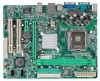
Motherboard Manual 1.5 MOT HERBOARD LAYOUT JKB MS1 LGA775 JCFAN1 COJMC1OM1 CPU1 JATXPWR1 JVGA1 DIMM1 DIMM2 JPRNT1 JUSB1 JUSBV1 JATXPWR2 J US BLAN1 P4M900 IDE1 IDE2 JAUDIO1 LAN PCI-E X16 Super I/O BAT1 PCI-EX1_1 JCDIN1 Codec JAUDIOF1 PCI1 PCI2 BIOS JU SB2 VIA VT8237A JUSB3 - Biostar P4M900-M7 FE | Setup Manual - Page 7
P4M900-M7 FE CHAPTER 2: HARDWARE INSTALLATION 2.1 INST ALLING CENT RAL PROCESSING UNIT (CPU) Special Notice: Remove Pin Cap before installation, and make good preservation for future use. When the CPU is removed, cover the Pin Cap on the empty socket to ensure pin legs won't be damaged. Pin Cap Step - Biostar P4M900-M7 FE | Setup Manual - Page 8
Motherboard Manual Step 2: Look for the triangular cut edge on socket, and the golden dot on CPU should point forwards this triangular cut edge. The CPU will fit only in the correct orientation. Step 2-1: Step 2-2: Step 3: Hold the CPU down firmly, and then lower the lever to locked position to - Biostar P4M900-M7 FE | Setup Manual - Page 9
P4M900-M7 FE 2.2 FAN HEADERS These fan headers support cooling-fans built in the computer. The 1 Ground 2 +12V 3 FAN RPM rate sense 3 1 Note: The JSFAN1 supports 3-pin head connector and the JCFAN1 supports 4-pin head connector. When connecti ng with wires onto connectors, pl ease note that - Biostar P4M900-M7 FE | Setup Manual - Page 10
DIMM1 DIMM2 Motherboard Manual 2.3 INST ALLING SYST EM MEMORY A. Memory Modules 1. Unlock a DIMM slot by pressing the retaining clips outward. Align a DIMM on the slot such that the notch on the DIMM matches the break on the Slot. 10 - Biostar P4M900-M7 FE | Setup Manual - Page 11
P4M900-M7 FE 2. Insert the DIMM vertically and firmly into the slot until the retaining chip snap back in place and the DIMM is properly seated. B. Memory Capacity DIMM Socket Location DIMM1 DIMM2 DDR Module 256MB/512MB/1GB/2GB 256MB/512MB/1GB/2GB Total Memory Size Max is 4GB. 11 - Biostar P4M900-M7 FE | Setup Manual - Page 12
Motherboard Manual 2.4 CONNECT ORS AND SLOT S FDD1: Floppy Disk Conne ctor The motherboard prov ides a standard floppy disk connector that supports 360K, 720K, 1.2M, 1.44M and 2.88M floppy disk ty pes. This connector supports the prov ided f loppy drive ribbon cable. 2 34 1 33 IDE1/IDE2: Hard - Biostar P4M900-M7 FE | Setup Manual - Page 13
P4M900-M7 FE PCI- er bandwidth up to 250MB/s per direction; 500MB/s in total. - PCI-Express supports a raw bit-rate of 2.5Gb/s on the data pins. - 2X bandwidth ov 1_1 PCI1/PCI2: Pe riphe ral Component Inte rconne ct Slots This motherboard is equipped with 2 standard PCI slots. PCI stands f or - Biostar P4M900-M7 FE | Setup Manual - Page 14
Motherboard Manual CHAPTER 3: HEADERS & JUMPERS SETUP 3.1 HOW T O SET UP JUMPERS The illustration shows how to set up jumpers. When the jumper cap is placed on pins, the - Biostar P4M900-M7 FE | Setup Manual - Page 15
P4M900-M7 FE ATX Powe r Source Conne ctor: JATXPWR1 JATXPWR1 allows user to connect 24-pin power 12 +3.3V JATXPWR2: ATX Powe r Source C onne ctor By connecting this connector, it will provide +12V to CPU power circuit. Pin Assignment 1 4 1 +12V 2 +12V 2 3 3 Ground 4 Ground 15 - Biostar P4M900-M7 FE | Setup Manual - Page 16
Motherboard Manual ATA Conne ctors The motherboard has a PCI to SATA Controller with 2 channels SATA interf ace, it satisfies the SATA 1.0 spec and with transfer Audio Heade r This header allows user to connect the front audio output cable with the PC f ront panel. This header allows only HD audio - Biostar P4M900-M7 FE | Setup Manual - Page 17
P4M900-M7 FE JCDIN1: CD-RO M Audio-in Connector This connector allows user to connect the audio source f rom the v ariaty dev it allows user to restore the BIOS saf e setting and the CMOS data, please carefully f ollow the procedures to avoid damaging the motherboard. 13 Pin 1-2 Close: Normal - Biostar P4M900-M7 FE | Setup Manual - Page 18
Motherboard Manual JPRNT1: Printe r Port Connector This header allows you to connector printer on the PC. 25 2 1 Pin Assignment 1 -Strobe 2 -ALF 3 Data 0 4 -Error 5 Data 1 6 -Init 7 Data 2 8 -Scltin 9 - Biostar P4M900-M7 FE | Setup Manual - Page 19
P4M900-M7 FE JUSBV1/JUSBV2: Powe r Source Heade rs for USB Ports Pin 1-2 Close: JUSBV1: +5V for 13 13 Pin 1-2 close JU SBV 2 13 13 Pin 2-3 close Note: In order to support this function "Power-On system via USB device," "JUSBV1/ JUSBV2" jumper cap should be placed on Pin 2-3 indi viduall y. 19 - Biostar P4M900-M7 FE | Setup Manual - Page 20
Motherboard Manual CHAPTER 4: RAID FUNCTIONS 4.1 OPERAT ION SYST EM z Supports Windows XP Home/Prof essional Edition, and Windows 2000 Prof essional. 4.2 RAID ARRAYS RAID supports the following types of RAID arrays: RAID 0: RAID 0 defines a disk striping scheme that improves disk read and write - Biostar P4M900-M7 FE | Setup Manual - Page 21
P4M900-M7 FE RAID 1: Every read and write is actually carried out in parallel can be applied for high-availability solutions, or as a form of automatic backup that eliminates tedious manual backups to more expensive and less reliable media. Features and Benefits Drives: Minimum 2, and maximum - Biostar P4M900-M7 FE | Setup Manual - Page 22
for better system performance. You will see the following window after you insert the CD T he setup guide will auto detect your motherboard and operating system. Note: If this window didn't show up after you insert the Driver CD, please use file browser to locate and execute the file SETUP.EXE - Biostar P4M900-M7 FE | Setup Manual - Page 23
5.2 AWARD BIOS BEEP CODE P4M900-M7 FE Beep Sound One long beep followed by two short beeps Meaning Video card not found or v ideo card memory bad High-low siren sound CPU overheated System will shut down automatically One Short beep when system boot-up No error found during POST Long beeps - Biostar P4M900-M7 FE | Setup Manual - Page 24
Motherboard Manual 5.4 TROUBLESHOOT ING Probable Solution 1. No power to the system at all 1. Make sure power cable is Power light don't illuminate, f an securely plugged in. inside power supply does not turn 2. Replace cable. on. 3. Contact technical support. 2. Indicator light on key - Biostar P4M900-M7 FE | Setup Manual - Page 25
P4M900-M7 FE This page is intentionally left blank. 25 - Biostar P4M900-M7 FE | Setup Manual - Page 26
Motherboard Manual APPENDENCIES: SPEC IN OTHER LANGUAGE GERMAN Spezifikationen LGA 775 Intel Core2Duo/ Pe ntium 4 / Pentium Unterstützt Hyper -Threadi ng / Execute Disable Bit CPU D / C eleron D / Celer on 4xx Prozessoren mit bis zu 3,8 GHz / Enha nced I ntel Spee dStep® / Intel Architecture - Biostar P4M900-M7 FE | Setup Manual - Page 27
P4M900-M7 FE Spezifikationen SATA-Anschluss x2 Jeder A nschluss unterstützt 1 SATA-Laufwerk Fronttafela nschluss x1 Unterstützt die Fro nttafelfunktio nen Front-Audioa nschluss x1 Unterstützt die Fronttafel-Audioa nschlussfunktion CD-IN-Anschluss x1 Unterstützt die CD Audio-I n-Funktion - Biostar P4M900-M7 FE | Setup Manual - Page 28
Motherboard Manual FRANCE SPEC LGA consumption. Bus frontal 533 / 800 / 1066 MHz Chipset VIA P4M900 VIA VT8237A Graphi que Chrome9 HC 3D / 2D Graphics s audio ALC662 10 / 100 Mb/s négociation a utomatique Half / Full duplex capability Prise en c harge de l'audio haute dé finition Sortie audio - Biostar P4M900-M7 FE | Setup Manual - Page 29
P4M900-M7 FE SPEC Connecteur IDE Chaque connecteur prend e n char ge 2 audio x3 Dimension s de la 190 mm (l) X 244 mm (H) carte Fonctionna lités Prise en c harge RAID 0 / 1 spéciales Support SE Windows 2K / XP / VISTA Biostar se réserve le droit d'ajo uter o u de supprimer le support - Biostar P4M900-M7 FE | Setup Manual - Page 30
Motherboard Manual IT ALIAN SPECIFICA CPU use processors Memory 64 with 95W power consumption. 533 / 800 / 1066 MHz Chipset Grafica VIA P4M900 VIA VT8237A Chrome9 audio ALC662 Negoziazione automatica 10 / 100 Mb/s Capacità Half / Full Duplex Supporto audio High-Definition (HD) Uscita audio - Biostar P4M900-M7 FE | Setup Manual - Page 31
P4M900-M7 FE SPECIFICA Connettore SATA x2 Ciascun connettore supporta 1 unità SATA Connettore pa nnello fro ntale x1 Supporta i servizi del pa nnell o fr ontale Connettore audio frontale x1 Supporta la funzione audi o pannello frontale Connettore CD-in Collettore ventolina CPU x1 - Biostar P4M900-M7 FE | Setup Manual - Page 32
Motherboard Manual SPANISH Especificación CPU FSB LGA 775 Procesador I ntel Core 2Duo / Penti um Admite Hyper -Threadi ng / 95W power consumption. 533 / 800 / 1066 MHz Conju nto de chips Gráficos VIA P4M900 VIA VT8237A Chrome9 HC 3D / 2D Graphics Memoria máxima de vídeo compartida de 256MB - Biostar P4M900-M7 FE | Setup Manual - Page 33
P4M900-M7 FE ntilador de C PU X1 Fuente de alime ntación de ve ntilador de CPU (con funció n Smart Fan) Cabecera de ve ntilador de sistema Fuente placa Funciones Admite RAID 0 / 1 especiales Soporte de sistema Windows 2K / XP / VISTA operativo Biostar se reserva el derecho de aña dir o r etirar - Biostar P4M900-M7 FE | Setup Manual - Page 34
Motherboard Manual PORT UGUESE ESPECIFICAÇÕES CPU FSB LGA . 533 / 800 / 1066 MHz Chipset Placa gráfica VIA P4M900 VIA VT8237A Chrome9 HC 3D / 2D Graphics Memória de ví de dados até 1.5 Gb/s. Compatibilidade com a especificação SATA versão 1.0. LAN PHY Realtek RTL 8201CL PH Y Codec de ALC662 - Biostar P4M900-M7 FE | Setup Manual - Page 35
P4M900-M7 FE o a partir de C Ds Conector da ve ntoinha da CPU x1 Alimentação da ventoi nha da CPU (com a função Smart Fan) Conector da ve ntoinha funções RAID 0 / 1 especiais Sistemas operativos Windows 2K / XP / VISTA suportado s A Biostar reserva-se o direito de adicionar ou remover suporte - Biostar P4M900-M7 FE | Setup Manual - Page 36
Motherboard Manual POLISH SPEC Procesor FSB LGA 775 Procesor Intel Cor e2Duo/ Penti um 4 / Obsługa Hyper -Threa ding / Execute Disa ble Bit Pentium D / Celeron D / Celer on 4xx do / Enha nced I ntel Spee dStep® / Intel 3,8 GHz Architecture-64 / Exte nde d Memory 64 *It is recommende d to - Biostar P4M900-M7 FE | Setup Manual - Page 37
190 mm (S) X 244 mm (W) płyty Funkcje Obsługa RAID 0 / 1 specjalne O bs luga systemu Windows 2K / XP / VISTA operacyjn ego P4M900-M7 FE SPEC x1 Obsługa eleme ntów pa nela przedniego x1 Obsługa funkcji audio na pa nelu przednim x1 Obsługa funkcji wejścia a udio CD Zasilanie wentylatora - Biostar P4M900-M7 FE | Setup Manual - Page 38
Motherboard Manual RUSSIAN СПЕЦ LGA 775 CPU Intel Core 2Duo/ Pe ntium Hy per-Thre ading / 4 / Pentium D / Celero n D y 64 Technology with 95W power consumption. FSB 533 / 800 / 1066 МГц VIA P4M900 VIA VT8237A Chrome9 HC 3D / 2D Graphics 256 МБ Super I/O Слоты DDR2 DIMM - Biostar P4M900-M7 FE | Setup Manual - Page 39
P4M900-M7 FE СПЕЦ SATA 1 x2 SATA x1 x1 CD x1 CD x1 x1 CMOS x1 USB Порт LAN x1 USB-порт x4 а x3 190 мм (Ш ) X 244 мм (В) е RAID 0 / 1 ики Windows 2K / XP / VISTA OS Biostar OS 39 - Biostar P4M900-M7 FE | Setup Manual - Page 40
Motherboard Manual ARABIC LGA 775 Intel Core2Duo/ Pe ntium 4 / Pentium Hyper -Thre ading / Exec ute Disabl e with 95W power co nsumption. 533 / 800 / 1066 256 VIA P4M900 VIA VT8237A Chrome9 HC 3D / 2D Graphics 2 DDR2 DIMM 533 / - Biostar P4M900-M7 FE | Setup Manual - Page 41
P4M900-M7 FE 2 1 1 PCI PCI Expressx16 PCI Express x 1 IDE SATA Smart Fan USB 1 1 1 VGA 1 4 USB 3 190 244 X RAID 0 / 1 Biostar Windows 2K / XP / VISTA 41 - Biostar P4M900-M7 FE | Setup Manual - Page 42
Motherboard Manual JAPANESE 仕様 CPU FSB LGA 775 Intel Core2Duo/ Pe ntium 4 / Pentium Hyper -Thre ading / Exec ute Disabl e Bit / D / Celero n D / C eleron 4xx processor Enha nced Intel SpeedStep® / I ntel up to 3.8 GHz Architecture-64 / Exte nde d Memory 64 *It is recommende d to use - Biostar P4M900-M7 FE | Setup Manual - Page 43
CD x1 CD CPU x1 CPU x1 CMOS x1 USBコネクタ 2 USB x2 24ピン) x1 4ピン) x1 PS/2 x1 PS/2マウス x1 x1 VGAポート x1 I/O LANポート x1 USBポート x4 x3 190 mm (幅) X 244 mm (高さ) ズ RAID 0 / 1 O Sサポー Windows 2K / XP / VISTA ト Bios tar O S 2007/11
-
 1
1 -
 2
2 -
 3
3 -
 4
4 -
 5
5 -
 6
6 -
 7
7 -
8
-
9
-
10
-
11
-
12
-
13
-
14
-
15
-
16
-
17
-
18
-
19
-
20
-
21
-
22
-
23
-
24
-
25
-
26
-
27
-
28
-
29
-
30
-
31
-
32
-
33
-
34
-
35
-
36
-
37
-
38
-
39
-
40
-
41
-
42
-
43
 |
 |

P4M900-M7 FE Setup Manual
FCC Information and Copyright
This equipment has been tested and found to comply with the limits of a Class
B digital device, pursuant to Part 15 of the FCC Rules. These limits are designed
to provide reasonable protection against harmful interference in a residential
installation. This equipment generates, uses, and can radiate radio frequency
energy and, if not installed and used in accordance with the instructions, may
cause harmful interference to radio communications. There is no guarantee
that interference will not occur in a particular installation.
The vendor makes no representations or warranties with respect to the
contents here and specially disclaims any implied warranties of merchantability
or fitness for any purpose. Further the vendor reserves the right to revise this
publication and to make changes to the contents here without obligation to
notify any party beforehand.
Duplication of this publication, in part or in whole, is not allowed without first
obtaining the vendor’s approval in writing.
The content of this user’s manual is subject to be changed without notice and
we will not be responsible for any mistakes found in this user’s manual. All the
brand and product names are trademarks of their respective companies.