Biostar P4M900-M7 FE Setup Manual - Page 5
Rear Panel Connect Ors - for windows 7
 |
View all Biostar P4M900-M7 FE manuals
Add to My Manuals
Save this manual to your list of manuals |
Page 5 highlights
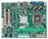
Front Pa nel Co nnector Front Audi o Co nnector CD-in Co nnector CPU Fan hea der System Fan hea der Clear CMOS header USB connector Power Connector ( 24pi n) Power Connector ( 4pin) PS/2 Keyboard PS/2 Mo use Serial Port Back Panel VGA Port I/O LAN port USB Port Audio J ack Board Size 190 mm (W) x 244 mm (L) Special Feature RAID 0 / 1 support OS Support Windows 2000 / XP / VISTA P4M900-M7 FE SPEC x1 Supports front panel facilities x1 Supports front panel a udio function x1 Supports CD audio-in function x1 CPU Fan power s upply (with Smart Fa n function) x1 System Fan Power supply x1 Restore CMOS data to factory defa ult x2 Each connector supports 2 fr ont panel USB ports x1 Connects to Power supply x1 Connects to Power supply x1 Connects to PS/ 2 Key board x1 Connects to PS/ 2 Mo use x1 Provide RS- 232 Serial connection x1 Connects to mo nitor. x1 Connects to RJ- 45 ether net cable x4 Connects to USB devices x3 Provide Audio-In/Out a nd microphone co nnection Micro ATX Size Board Biostar Reserves the right to a dd or r emove support for any OS with or witho ut notice. 1.4 REAR PANEL CONNECT ORS PS /2 Mouse LA N Li ne In/ Surround Line Out Mic I n 1/ Bass/ Center PS/ 2 Keyboard COM1 V GA USBX2 USBX2 Since the audio c hip s upports High Definiti on Audio Specific ation, the func tion of eac h audi o jack c an be defined by software. T he input / output function of each audio jac k listed above represents the default s etti ng. However, when c onnecti ng exter nal microphone to the audio port, pleas e us e the Line In (blue) and Mic In (Pink) audio j ac k. 5
-
 1
1 -
 2
2 -
 3
3 -
 4
4 -
 5
5 -
 6
6 -
 7
7 -
 8
8 -
 9
9 -
 10
10 -
 11
11 -
12
-
13
-
14
-
15
-
16
-
17
-
18
-
19
-
20
-
21
-
22
-
23
-
24
-
25
-
26
-
27
-
28
-
29
-
30
-
31
-
32
-
33
-
34
-
35
-
36
-
37
-
38
-
39
-
40
-
41
-
42
-
43
 |
 |
