Biostar P4M900-M7 FE Setup Manual - Page 12
FDD1: Floppy Disk Connector, IDE1/IDE2: Hard Disk Connectors
 |
View all Biostar P4M900-M7 FE manuals
Add to My Manuals
Save this manual to your list of manuals |
Page 12 highlights
Motherboard Manual 2.4 CONNECT ORS AND SLOT S FDD1: Floppy Disk Conne ctor The motherboard prov ides a standard floppy disk connector that supports 360K, 720K, 1.2M, 1.44M and 2.88M floppy disk ty pes. This connector supports the prov ided f loppy drive ribbon cable. 2 34 1 33 IDE1/IDE2: Hard Disk Conne ctors The motherboard has a 32-bit Enhanced PCI IDE Controller that prov ides PIO Mode 0~4, Bus Master, and Ultra DMA 33/66/100/133 f unctionality. It has two HDD connectors: IDE1 (primary ) and IDE2 (secondary ). The IDE connectors can connect a master and a slav e driv e, so you can connect up to four hard disk drives. The f irst hard drive should always be connected to IDE1. 40 39 2 1 IDE1 IDE2 12
-
 1
1 -
2
-
3
-
4
-
5
-
6
-
 7
7 -
 8
8 -
 9
9 -
 10
10 -
 11
11 -
 12
12 -
 13
13 -
 14
14 -
 15
15 -
 16
16 -
 17
17 -
18
-
19
-
20
-
21
-
22
-
23
-
24
-
25
-
26
-
27
-
28
-
29
-
30
-
31
-
32
-
33
-
34
-
35
-
36
-
37
-
38
-
39
-
40
-
41
-
42
-
43
 |
 |

Motherboard Manual
12
2.4
C
ONNECTORS AND
S
LOTS
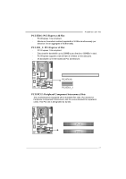
FDD1: Floppy Disk Connector
The motherboard provides a standard floppy disk connector that supports 360K,
720K, 1.2M, 1.44M and 2.88M floppy disk types. This connector supports the
provided floppy drive ribbon cable.
34
33
1
2
IDE1/IDE2: Hard Disk Connectors
The motherboard has a 32-bit Enhanced PCI IDE Controller that provides PIO
Mode 0~4, Bus Master, and Ultra DMA 33/66/100/133 functionality. It has two
HDD connectors: IDE1 (primary) and IDE2 (secondary).
The IDE connectors can connect a master and a slave drive, so you can
connect up to four hard disk drives. The first hard drive should always be
connected to IDE1.
IDE2
IDE1
2
1
39
40