Biostar TA990FXE Setup Manual - Page 44
Checkpoint, Description - ram
 |
View all Biostar TA990FXE manuals
Add to My Manuals
Save this manual to your list of manuals |
Page 44 highlights
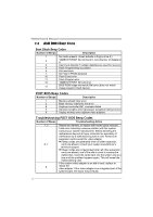
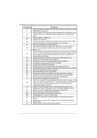
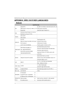
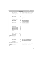
Motherboard Manual Checkpoint Description 37 Displaying sign-on message, CPU information, setup key message, and any OEM specific information. Initializes different devices through DIM. See DIM Code Checkpoints section 38 of document for more information. USB controllers are initialized at this point. 39 Initializes DMAC-1 & DMAC-2. 3A Initialize RTC date/time. 3B Test for total memory installed in the system. Also, Check for DEL or ESC keys to limit memory test. Display total memory in the system. 3C Mid POST initialization of chipset registers. Detect different devices (Parallel ports, serial ports, and coprocessor in 40 CPU, etc.) successfully installed in the system and update the BDA, EBDA...etc. Updates CMOS memory size from memory found in memory test. Allocates 52 memory for Extended BIOS Data Area from base memory. Programming the memory hole or any kind of implementation that needs an adjustment in system RAM size if needed. 60 Initializes NUM-LOCK status and programs the KBD typematic rate. 75 Initialize Int-13 and prepare for IPL detection. 78 Initializes IPL devices controlled by BIOS and option ROMs. 7C Generate and write contents of ESCD in NVRam. 84 Log errors encountered during POST. 85 Display errors to the user and gets the user response for error. 87 Execute BIOS setup if needed / requested. Check boot password if installed. 8C Late POST initialization of chipset registers. 8D Build ACPI tables (if ACPI is supported). 8E Program the peripheral parameters. Enable/Disable NMI as selected. 90 Initialization of system management interrupt by invoking all handlers. Please note this checkpoint comes right after checkpoint 20h. A1 Clean-up work needed before booting to OS. Takes care of runtime image preparation for different BIOS modules. Fill the A2 free area in F000h segment with 0FFh. Initializes the Microsoft IRQ Routing Table. Prepares the runtime language module. Disables the system configuration display if needed. A4 Initialize runtime language module. Display boot option popup menu. A7 Displays the system configuration screen if enabled. Initialize the CPU's before boot, which includes the programming of the MTRR's. A9 Wait for user input at config display if needed. AA Uninstall POST INT1Ch vector and INT09h vector. AB Prepare BBS for Int 19 boot. Init MP tables. AC End of POST initialization of chipset registers. De-initializes the ADM module. B1 Save system context for ACPI. Prepare CPU for OS boot including final MTRR values. 00 Passes control to OS Loader (typically INT19h). 42
-
 1
1 -
2
-
3
-
4
-
5
-
6
-
7
-
8
-
9
-
10
-
11
-
12
-
13
-
14
-
15
-
16
-
17
-
18
-
19
-
20
-
21
-
22
-
23
-
24
-
25
-
26
-
27
-
28
-
29
-
30
-
31
-
32
-
33
-
34
-
35
-
36
-
37
-
38
-
 39
39 -
 40
40 -
 41
41 -
 42
42 -
 43
43 -
 44
44 -
 45
45 -
 46
46 -
 47
47 -
 48
48 -
 49
49 -
50
-
51
-
52
-
53
-
54
-
55
-
56
-
57
-
58
-
59
-
60
-
61
-
62
-
63
-
64
-
65
 |
 |