Biostar TZ77B Setup Manual - Page 15
PCI1/PCI2: Peripheral Component Interconnect Slots, ATXPWR2: ATX Power Source Connectors
 |
View all Biostar TZ77B manuals
Add to My Manuals
Save this manual to your list of manuals |
Page 15 highlights
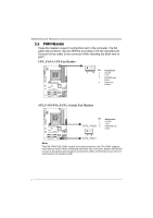
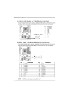
TZ77B/TZ75B/T77 PCI1/PCI2: Peripheral Component Interconnect Slots This motherboard is equipped with 2 standard PCI slots. PCI stands for Peripheral Component Interconnect, and it is a bus standard for expansion cards. This PCI slot is designated as 32 bits. PCI 1 P CI2 ATXPWR2: ATX Power Source Connectors These connectors provide +12V to CPU power circuit. If the CPU power plug is 4-pin, please plug it into Pin 1-2-5-6 of ATXPWR2. 8 4 Pin Assignment 1 +12V 2 +12V 5 13 +12V 4 +12V 5 Ground 6 Ground 7 Ground 8 Ground 13
-
 1
1 -
2
-
3
-
4
-
5
-
6
-
7
-
8
-
9
-
 10
10 -
 11
11 -
 12
12 -
 13
13 -
 14
14 -
 15
15 -
 16
16 -
 17
17 -
 18
18 -
 19
19 -
 20
20 -
21
-
22
-
23
-
24
-
25
-
26
-
27
-
28
-
29
-
30
-
31
-
32
-
33
-
34
-
35
-
36
-
37
-
38
-
39
-
40
-
41
-
42
-
43
-
44
-
45
-
46
-
47
-
48
-
49
-
50
-
51
-
52
-
53
-
54
-
55
-
56
-
57
-
58
-
59
-
60
-
61
-
62
-
63
-
64
-
65
 |
 |

TZ77B/TZ75B/T77
13
PCI1/PCI2: Peripheral Component Interconnect Slots
This motherboard is equipped with 2 standard PCI slots. PCI stands for
Peripheral Component Interconnect, and it is a bus standard for expansion
cards. This PCI slot is designated as 32 bits.
PCI2
PCI1
ATXPWR2: ATX Power Source Connectors
These connectors provide +12V to CPU power circuit.
If the CPU power plug is
4-pin, please plug it into Pin 1-2-5-6 of ATXPWR2.
Pin
Assignment
1
+12V
2
+12V
3
+12V
4
+12V
5
Ground
6
Ground
7
Ground
1
4
8
5
8
Ground