Biostar TZ77B Setup Manual - Page 19
F_AUDIO1: Front Panel Audio Header, JSPDIFOUT1: Digital Audio-out Connector, CIR1: Consumer IR
 |
View all Biostar TZ77B manuals
Add to My Manuals
Save this manual to your list of manuals |
Page 19 highlights
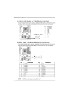
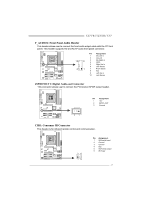
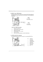
TZ77B/TZ75B/T77 F_AUDIO1: Front Panel Audio Header This header allows user to connect the front audio output cable with the PC front panel. This header supports HD and AC'97 audio front panel connector. Pin Assignment 1 Mic Left in 2 Ground 10 9 3 Mic Right in 4 GPIO 5 Right line in 6 Jack Sense 2 1 7 Front Sense 8 Key 9 Left line in 10 Jack Sense JSPDIFOUT1: Digital Audio-out Connector This connector allows user to connect the PCI bracket SPDIF output header. Pin Assignment 1 +5V 2 SPDIF_OUT 3 Ground 3 1 CIR1: Consumer IR Connector This header is for infrared remote control and communication. 26 15 Pin Assignment 1 IrDA serial input 2 Ground 3 Ground 4 Key 5 IrDA serial output 6 IR Power 17
-
 1
1 -
2
-
3
-
4
-
5
-
6
-
7
-
8
-
9
-
10
-
11
-
12
-
13
-
 14
14 -
 15
15 -
 16
16 -
 17
17 -
 18
18 -
 19
19 -
 20
20 -
 21
21 -
 22
22 -
 23
23 -
 24
24 -
25
-
26
-
27
-
28
-
29
-
30
-
31
-
32
-
33
-
34
-
35
-
36
-
37
-
38
-
39
-
40
-
41
-
42
-
43
-
44
-
45
-
46
-
47
-
48
-
49
-
50
-
51
-
52
-
53
-
54
-
55
-
56
-
57
-
58
-
59
-
60
-
61
-
62
-
63
-
64
-
65
 |
 |

TZ77B/TZ75B/T77
17
F_AUDIO1: Front Panel Audio Header
This header allows user to connect the front audio output cable with the PC front
panel. This header supports HD and AC’97 audio front panel connector.
Pin
Assignment
1
Mic Left in
2
Ground
3
Mic Right in
4
GPIO
5
Right line in
6
Jack Sense
7
Front Sense
8
Key
9
Left line in
1
2
9
10
10
Jack Sense
JSPDIFOUT1: Digital Audio-out Connector
This connector allows user to connect the PCI bracket SPDIF output header.
Pin
Assignment
1
+5V
2
SPDIF_OUT
1
3
3
Ground
CIR1: Consumer IR Connector
This header is for infrared remote control and communication.
Pin
Assignment
1
IrDA serial input
2
Ground
3
Ground
4
Key
5
IrDA serial output
6
IR Power
1
2
5
6