Bosch 1873-8 Operating Instructions - Page 8
FIG. 1, FIG. 2, FIG. 3 - parts
 |
UPC - 000346342864
View all Bosch 1873-8 manuals
Add to My Manuals
Save this manual to your list of manuals |
Page 8 highlights
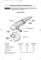
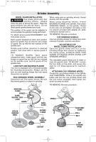
BM 1609929H54 08-06 8/3/06 11:44 AM Page 8 MOUNTING TYPE 28 OR TYPE 29 GRINDING WHEELS ! WARNING To reduce the risk of injury, do not use the flange set provided with your tool for mounting type 28 or type 29 grinding wheels. The flanges provided with your tool are not designed for mounting these wheels. Only use small flange set (available as accessory) when mounting type 28 or type 29 wheels (Fig. 1). Refer to figures 2 or 3 for proper wheel assembly when using the small flange set. SMALL FLANGE SET PART NO. 1 607 000 380 FIG. 1 FLANGE WITH SHOULDER FLANGE OR LOCK NUT FIG. 2 SPINDLE FLANGE WITH SHOULDER TYPE 28 GRINDING WHEEL FLANGE OR LOCK NUT FIG. 3 SPINDLE FLANGE OR LOCK NUT FLANGE WITH SHOULDER -8- TYPE 29 GRINDING WHEEL
-
 1
1 -
2
-
 3
3 -
 4
4 -
 5
5 -
 6
6 -
 7
7 -
 8
8 -
 9
9 -
 10
10 -
 11
11 -
 12
12 -
 13
13 -
14
-
15
-
16
-
17
-
18
-
19
-
20
-
21
-
22
-
23
-
24
-
25
-
26
-
27
-
28
-
29
-
30
-
31
-
32
-
33
-
34
-
35
-
36
 |
 |

MOUNTING TYPE 28 OR TYPE 29
GRINDING WHEELS
To reduce the risk of injury,
do not use the flange set
provided with your tool for mounting type
28 or type 29 grinding wheels.
The flanges
provided with your tool are not designed for
mounting these wheels.
Only use small flange set (available as
accessory) when mounting type 28 or type 29
wheels (Fig. 1).
Refer to figures 2 or 3 for proper wheel
assembly when using the small flange set.
-8-
SMALL FLANGE SET
PART NO.
1 607 000 380
FLANGE WITH
SHOULDER
FLANGE OR LOCK NUT
FIG. 1
FLANGE WITH SHOULDER
FLANGE OR LOCK NUT
TYPE 28
GRINDING WHEEL
SPINDLE
FIG. 2
FLANGE WITH SHOULDER
FLANGE OR LOCK NUT
TYPE 29
GRINDING
WHEEL
SPINDLE
FIG. 3
!
WARNING
BM 1609929H54 08-06
8/3/06
11:44 AM
Page 8