Bosch 1873-8 Operating Instructions - Page 9
Operating Instructions, Sander Assembly - 7 grinder
 |
UPC - 000346342864
View all Bosch 1873-8 manuals
Add to My Manuals
Save this manual to your list of manuals |
Page 9 highlights
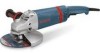
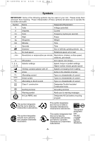
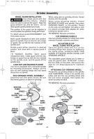
BM 1609929H54 08-06 8/3/06 11:44 AM Page 9 Sander Assembly BACKING PAD ! WARNING Before attaching a backing pad be sure its maximum safe operating speed is not exceeded by the nameplate speed of the tool. ! WARNING Wheel guard may not be used for most sanding operations. Always reinstall wheel guard when converting back to grinding operations. TO INSTALL BACKING PAD AND SANDING DISC Disconnect tool from power source. Set the tool on its top side (spindle up). Place the rubber backing pad onto the spindle shaft. Center the sanding disc on top of the backing pad. Insert the lock nut through the disc and thread onto the spindle as far as you can with your fingers. Press in the spindle lock, then tighten the backing pad securely with lock nut wrench. TO REMOVE BACKING PAD AND SANDING DISC Disconnect tool from power source. Using the lock nut wrench unscrew the nut from the spindle, while holding spindle lock in. WIRE BRUSH ASSEMBLY Before assembling wire brush to this tool, disconnect from the power source. Wire brushes are equipped with their own threaded hub, simply thread on to spindle. Be sure to seat against shoulder before turning tool "ON". SIDE HANDLE The side handle used to guide and balance the tool can be threaded into the front housing on either side, and on top of the tool, depending on personal preference and comfort. Use the side handle for safe control and ease of operation. ! WARNING Always handle use auxiliary for maximum control over torque reaction or kick-back. Operation of the grinder without the side handle could cause loss of control of the grinder, resulting in possible serious personal injury. SPINDLE LOCK SPINDLE RUBBER BACKING PAD SPIN-ON WIRE BRUSH SANDING DISC LOCK NUT Operating Instructions "TRI-CONTROL" PADDLE SWITCH The "Tri-Control" Paddle Switch enables the operator to control the switch functions of "Lock-OFF", "ON/OFF" and "Lock-ON". TO UNLOCK SWITCH AND TURN TOOL "ON": Push paddle lever FORWARD (toward the spindle) then squeeze the paddle lever. TO SWITCH TOOL "OFF": Release pressure on paddle lever. The switch is spring loaded and will return to "OFF" position automatically. The "Lock-ON" feature, incorporated into the paddle switch, is a convenience for long operations. TO LOCK SWITCH "ON": After paddle switch has been activated push paddle lever completely FORWARD and release paddle lever. TO SWITCH TOOL "OFF": Squeeze and then release paddle lever. The switch is spring loaded and will return to "OFF" position automatically. ! WARNING Hold the tool with both hands while starting the tool, since torque from the motor can cause the tool to twist. -9-
-
 1
1 -
2
-
3
-
 4
4 -
 5
5 -
 6
6 -
 7
7 -
 8
8 -
 9
9 -
 10
10 -
 11
11 -
 12
12 -
 13
13 -
 14
14 -
15
-
16
-
17
-
18
-
19
-
20
-
21
-
22
-
23
-
24
-
25
-
26
-
27
-
28
-
29
-
30
-
31
-
32
-
33
-
34
-
35
-
36
 |
 |