Bosch NGT745UC Installation Instructions - Page 9
Before Calling Service, Product Data Plate - burners
 |
View all Bosch NGT745UC manuals
Add to My Manuals
Save this manual to your list of manuals |
Page 9 highlights
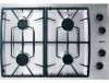
6) Connect Electrical Supply 7) Final Check • The appliance must be isolated from the gas supply piping system by closing its individual manual shut-off valve during any pressure testing of the gas supply piping system at test pressures equal to or less than 1/2 psi (3.5kPa). Before connecting 5-foot (1.5 m) supply cord to wall receptacle, make certain that gas shutoff valve and all burner controls are in OFF position. After electrical connection is complete, place each burner cap in correct sized notched position and check operation of electric igniters. Check flame characteristics. Flame should be blue with no yellow tip. Before Calling Service Product Data Plate Yellow Flames: Further adjustment is required. Yellow Tips on Outer Cones: Normal for LP Gas. Soft Blue Flames: Normal for Natural Gas. If the flame is completely or mostly yellow, verify that the regulator is set for the correct fuel. After adjustment, retest. Some yellow streaking is normal during the initial start-up. Allow unit to oper- If the elements do not heat or if the indicator "on" light does not glow, check the power source to see if a fuse has blown or if the circuit breaker has tripped. Refer to the Warranty in the Use and Care Manual. See Use and Care manual for troubleshooting information. The data plate shows the model and serial number of your cooktop. It is located in the center front area of the rough-in box, underneath the cooktop. Keep your invoice or escrow papers for warranty validation if service is needed. English 7
-
 1
1 -
2
-
3
-
 4
4 -
 5
5 -
 6
6 -
 7
7 -
 8
8 -
 9
9 -
 10
10 -
 11
11 -
 12
12 -
 13
13 -
 14
14 -
15
-
16
-
17
-
18
-
19
-
20
-
21
-
22
-
23
-
24
-
25
-
26
-
27
-
28
 |
 |
