Bosch VDC-455V04-20 Installation Instructions - Page 10
Installation Manual - camera 10
 |
View all Bosch VDC-455V04-20 manuals
Add to My Manuals
Save this manual to your list of manuals |
Page 10 highlights
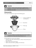
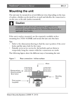
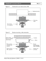
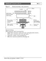
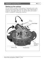
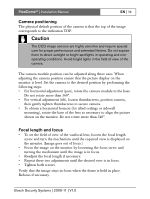
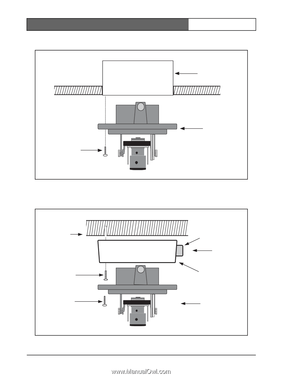
FlexiDomeVF | Installation Manual Figure 2 Connection to an electrical box (4S) EN | 10 S4 Electrical box Two screws (not supplied) Mounting base Figure 3 Surface mounting - side connection Solid surface (three pre-drilled 8mm holes) Three screws (supplied with camera) Three screws (M5, supplied) Conduit Wires Raised mounting base (VDA-445SMB) Camera unit and base Bosch Security Systems | 2005-11 | V1.0
-
 1
1 -
2
-
3
-
4
-
 5
5 -
 6
6 -
 7
7 -
 8
8 -
 9
9 -
 10
10 -
 11
11 -
 12
12 -
 13
13 -
 14
14 -
 15
15 -
16
-
17
-
18
-
19
-
20
-
21
-
22
-
23
-
24
-
25
-
26
-
27
-
28
-
29
-
30
-
31
-
32
-
33
-
34
-
35
-
36
-
37
-
38
-
39
-
40
-
41
-
42
-
43
-
44
-
45
-
46
-
47
-
48
-
49
-
50
-
51
-
52
-
53
-
54
-
55
-
56
-
57
-
58
-
59
-
60
-
61
-
62
-
63
-
64
-
65
-
66
-
67
-
68
-
69
-
70
-
71
-
72
-
73
-
74
-
75
-
76
-
77
-
78
-
79
-
80
-
81
-
82
-
83
-
84
-
85
-
86
-
87
-
88
-
89
-
90
-
91
-
92
-
93
-
94
-
95
-
96
-
97
-
98
-
99
-
100
-
101
-
102
-
103
-
104
-
105
-
106
-
107
-
108
-
109
-
110
-
111
-
112
-
113
-
114
-
115
-
116
-
117
-
118
-
119
-
120
-
121
-
122
-
123
-
124
-
125
-
126
-
127
-
128
-
129
-
130
-
131
-
132
-
133
-
134
-
135
-
136
-
137
-
138
-
139
-
140
-
141
-
142
-
143
-
144
-
145
-
146
-
147
-
148
-
149
-
150
-
151
-
152
-
153
-
154
-
155
-
156
-
157
-
158
-
159
-
160
-
161
-
162
-
163
-
164
-
165
-
166
-
167
-
168
-
169
-
170
-
171
-
172
-
173
-
174
-
175
-
176
-
177
-
178
-
179
-
180
-
181
-
182
-
183
-
184
-
185
-
186
-
187
-
188
-
189
-
190
-
191
-
192
-
193
-
194
-
195
-
196
 |
 |
FlexiDome
VF
| Installation Manual
Bosch Security Systems | 2005-11 | V1.0
EN
| 10
Figure 2
Connection to an electrical box (4S)
Figure 3
Surface mounting - side connection
S4 Electrical box
Two screws
(not supplied)
Mounting
base
Wires
Three screws
(M5, supplied)
Raised
mounting base
(VDA-445SMB)
Conduit
Three screws
(supplied with
camera)
Camera unit
and base
Solid surface
(three pre-drilled
8mm holes)