Bose 10.2 Series II Owner's guide - Page 4
Connecting, Series, Speaker, System
 |
View all Bose 10.2 Series II manuals
Add to My Manuals
Save this manual to your list of manuals |
Page 4 highlights
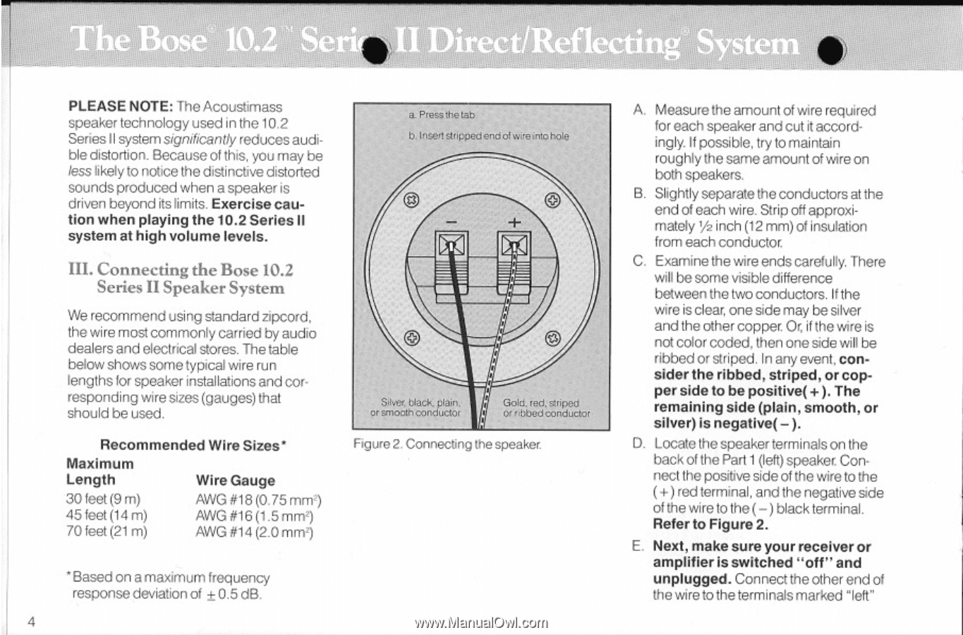
14 %1 k -I otabtalli=s IIWt II' PLEASE NOTE: The Acoustimass speaker technology used in the 10.2 SeriesII systemsignificantly reducesaudible distortion. Becauseof this, youmay be less likely to notice the distinctive distorted sounds produced when a speaker is driven beyond its limits. Exercise caution when playing the 10.2 Series II system at high volume levels. III. Connecting the Bose 10.2 Series II Speaker System We recommend using standard zipcord, the wire most commonly carried by audio dealers and electrical stores. The table below shows some typical wire run lengths for speaker installations and corresponding wire sizes(gauges) that should be used. Recommended Wire Sizes' Maximum Length Wire Gauge 30 feet (9 m) 45 feet (14 m) 70 feet (21m) AWG ri18 (0.75mmt) AWG #16(1.5mm2) AWG #14 (2.0mm2) a Press the tab U.IllSerlstnPnedendot %went°hole fi or sstmhroeof.tthiacocnkd. uctor Goroflidb.breeddc.ownipdeucdtor Figure 2. Connecting the speaker. "Based on a maximum frequency response deviation of ± 0.5 dB. 4 A. Measure the amount of wire required for each speaker andcut it accordingly. If possible, try tomaintain roughly the same amount of wire on both speakers. B. Slightly separate the conductors at the end of each wire. Strip off approximately y2 inch(12 mm)of insulation from each conductor. C. Examine the wire ends carefully. There will be some visible difference between the two conductors. If the wire is clear, onesidemay be silver and the other copper. Or, if the wire is not color coded, then one side will be ribbed or striped. In any event, consider the ribbed, striped, or copper side to be positive(+ ). The remaining side (plain, smooth, or silver) is negative( - ). D. Locate the speaker terminals on the back of thePart 1(left)speaker. Connect the positive side of the wire to the ( +)red terminal,andthe negative side of thewire to the(-) black terminal. Refer to Figure 2. E. Next, make sure your receiver or amplifier is switched "off" and unplugged. Connect the other end of the wire to the terminalsmarked "left"
-
 1
1 -
 2
2 -
 3
3 -
 4
4 -
 5
5 -
 6
6 -
 7
7 -
 8
8 -
 9
9 -
 10
10
 |
 |