Bose Acoustimass 5 Series II Owner's guide - Page 5
steps, superb, sound
 |
View all Bose Acoustimass 5 Series II manuals
Add to My Manuals
Save this manual to your list of manuals |
Page 5 highlights
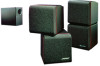
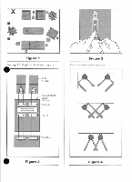
ca N" Five easy steps to superb sound Caution: Be sure to unplug your receiver or amplifier from the wall outlet before attempting to connect the Acoustimass'-5 system to it. Set up the system components. (Figure 1) Select the location for each of your Acoustimass system components. Place the Acoustimass module virtually anywhere in your listening room, in either a vertical or horizontal position (once this is determined, the protective rubber feet may be applied to the "bottom" of the module). It can be hidden under a bed or table or even behind a sofa. as long as you remember not to block the round opening in the end of the unit (allow at least 2 in. or 5 cm of space between that end and any surface.) Next, select the positions for the left and right cube arrays. Remember that wires from the arrays connect to the Acoustimass module, so you should locate the cube arrays close enough to the module to enable the wires to reach it. Note: While the wires provided are adequate for most installations, you may increase the distance between the cube arrays and the Acoustimass module by splicing in additional wire. If you do so, use similar gauge or thicker wire, and make sure you maintain the correct phase ("+" to "+" and "-" to --"), and properly connect the wires. 2 Examine the cables and connections. Locate the four identical sets of wires packed with the system. Two sets will connect your cube arrays to the Acoustimass module, while the other two sets will connect the Acoustimass module your receiver or amplifier. Examine the ends of the wires for each set, and make sure that you connect the wire with a red or striped marker to the "+" terminal for each COnneCtion. 3 Connect the cube arrays to the Acoustimass module. Select one pair of connector wires, and locate the terminals on the rear of the left cube array. Depress the red ("+") tab, insert the lead with the red or striped marker (Figure 2) and release the tab. The lead should be held snugly in place by the terminal. Repeat the process for the black terminal and the other lead. Follow the same procedure for the right cube array, using a second pair of wires. • 4
-
 1
1 -
 2
2 -
 3
3 -
 4
4 -
 5
5 -
 6
6 -
 7
7 -
 8
8 -
 9
9 -
 10
10 -
 11
11 -
12
-
13
-
14
 |
 |
