Bose L1 Compact Portable Line Array English Owners Guide - Page 12
Operating Information
 |
View all Bose L1 Compact Portable Line Array manuals
Add to My Manuals
Save this manual to your list of manuals |
Page 12 highlights
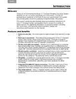
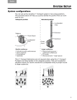
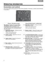
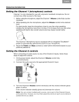
TAB TAB TAB TAB 4, 11 TAB 3, 10 TAB 2, 9, 16 English OPERATING INFORMATION Connections and controls The power stand control panel provides all the necessary connectors, controls, and indicators for operation. 1 2 3 4 5 12 7 8 10 6 9 11 Channel 1 (Microphone input) Channel 2 (Utility channel - multiple input) The channel 1 input is for use only with a microphone. Integrated ToneMatch® signal processing provides a high level of tone customization to provide a listening experience that most musicians can only achieve using a recording studio. 6. Signal/Clip indicator - Displays the input signal status in color. • Green: Input signal present • Red: Input signal clipping 1. Signal/Clip indicator - Displays the input signal status in color. • Green: Input signal present 7. Volume control - Adjusts the overall volume of all input sources connected to Channel 2. • Red: Input signal clipping 2. Volume control - Adjusts the volume of your microphone. 8. ⅛-inch (3.5 mm) stereo input - Analog input for connecting audio sources such as portable mp3 players, satellite radio, laptop computers, video projectors, and smart boards. 3. Treble control - Adjusts the amount of treble on your microphone. 9. RCA stereo input - Analog input for connecting audio sources such as DVD players, VCR players, video game consoles, DJ mixers, Keyboards and other instruments. For best results, connect both the left and right signals. 4. Bass control - Adjusts the amount bass on your microphone. 10. ¼-inch input - Balanced analog input for connecting guitars and other instruments. Accepts either ¼-inch TRS balanced or TS unbalanced cables. 5. Microphone input - Analog input for 11. ToneMatch® switch - When connecting an connecting a balanced XLR microphone cable. acoustic guitar to the ¼-inch input, move the A ToneMatch® microphone preset is built in. switch to the position to enable a ToneMatch® preset. When connecting anything other than an acoustic guitar to the ¼-inch input, move the switch down to the Line Level position. 12. Power LED - Indicates power status. Blue: Power on 6
-
 1
1 -
2
-
3
-
4
-
5
-
6
-
 7
7 -
 8
8 -
 9
9 -
 10
10 -
 11
11 -
 12
12 -
 13
13 -
 14
14 -
 15
15 -
 16
16 -
 17
17 -
18
-
19
-
20
-
21
-
22
-
23
-
24
 |
 |